
MS1/Extra Ignition Hardware Manual

The V2.2 and V3.0 PCBs are designed with spare connectors that facilitate the integration of various input and output devices, enhancing the versatility of the circuits. The 37-pin DB connector serves as a central interface, allowing for easy connectivity and expansion of the system. The absence of a prototyping area on the V3.57 PCB necessitates careful planning for any additional hardware modifications. Users are advised to create a daughter board to house any extra components needed for specific functionality, such as advanced ignition control or additional sensor inputs.
When working with the V3.57, attention must be given to the physical layout of the components, as the small size can complicate soldering and rework. Users should be equipped with appropriate tools and techniques to ensure reliable connections without damaging the PCB. The requirement for reinforcing traces is critical, especially in high-current applications where electrical integrity is paramount.
The timing control features provided by the V3.57 PCB are particularly beneficial for performance applications. The ability to utilize a single coil distributor with precise timing adjustments allows for enhanced engine performance and efficiency. The configuration of the crank trigger system must be executed with precision to ensure optimal firing sequences, which is vital for preventing misfires and optimizing combustion.
The detailed specifications regarding pulse requirements for various engine configurations highlight the importance of accurate signal generation and processing. The V3 board's compatibility with VR sensors and its built-in high-current driver simplifies the ignition system design, making it suitable for a range of automotive applications. Overall, the V2.2, V3.0, and V3.57 PCBs offer robust solutions for engine management and control, with careful consideration needed for installation and modifications to maximize their potential.The V2. 2 PCB has 4 spare connectors (X11 to X14) these can be used for various inputs and outputs for the following circuits as they are conveniently available on the 37pin DB connector: The V3. 0 PCB has 4 spare connectors (SPR1 to 4) these can be used for various inputs and outputs for the following circuits as they are conveniently available on
the 37pin DB connector: As can be seen, theres no proto area on the V3. 57 and the components are very small. So soldering wires onto the board for spark outputs, hardware options, etc, is going to need a great deal of care. You may even have to remove some parts, which is not easily done to surface mount components, so I don`t feel these manuals should cover doing this, as damage is very easy to do.
Also a daughter board will need to be built if you want some of the hardware options as theres no proto area to build on. I have therefore assumed if you bought a V3. 57 that you will not be modifying it to use the hardware functions such as Tacho out, PWM Idle valves, Boost control, Launch input, etc, etc.
If you do wish to use these then you will have to build a daughter board of some form to mount the components on. If you use more than 2 spark outputs youll need to use the db15 connector, but ensure you strengthen the traces on the board with copper wire or solder to the pin directly, also connect the outputs in pairs of pins, as per the instructions HERE.
Note that the JS0 - JS11 pads are all electrically the same as the V3. 0 PCB as are the SPR1 - 4 pads, so they can be used in the same way as the V3. 0 PCB. The addition is JS12 which is the same as the bottom of R1 on the V3. 0 pcb, but R1 will still need to be removed to use it on the V3. 57, so be very very carefull ! This mode is for use with a single coil distributor allowing you to control your timing if you have a single coil firing through a distributor, an MSD 6A amplifier, etc. This mode requires ONE Trigger per Spark Event, e. g. 2 pulses from a crank on a 4cy or 4 pulses from the disrtibutor on a 4cy (distributor runs at half the speed of the crank), 4 pulses from the crank on a V8 or 8 from the distributor on a V8, etc.
If your engine has a toothed wheel (e. g. a 60-2, 24/2, 36-1, etc) then you must NOT use MSnS mode, setup the WHEEL DECODER MODE instead, and select SparkA as the only spark output whilst using the distributor. A locked distributor is one that has mechanical and vacuum advance either removed or "locked" out so that the trigger signal occurs at the same crankshaft angle at all rpms.
Many distributor cars with EFI already have a locked distributor. Crank triggering provides a more stable advance as there is no timing chain or belt and distributor gear jitter. For a four cylinder engine you would require two pips/lobes or bolt heads (giving 2 signal pulses) at 180 degrees to each other and a VR / hall sensor, for a 6cy you will need 3 pulses per crank revolution at 120deg intervals and 4 for a V8 at 90deg intervals.
(note that a crank rotates at half the speed of the cam drive). The V3 circuit board can directly read from a VR sensor. The V3 board also provides a VB921 high current driver that will drive your single coil directly, this means you dont need an amplifier/dwell controller. If you use a crank trigger you do not need to modify your distributor. Just make sure that the internal rotor points towards one of the towers when the engine is roughly in the firing angle - if it is halfway you can easily get cross-firing between cylinders.
IMPORTANT - do NOT set your total Trigger Angle (i. e. Trigger Angle plus additions) inbetween the range 20 to 50 degrees as you will encounter problems and be unable to get your desired advance. If this is the Trigger Angle you calculate then you either need to move your crank sensor/wheel or modify your distributor to obtain a compatible trigger angle.
This is due to the way the ECU calculates the spark 🔗 External reference
Related Circuits
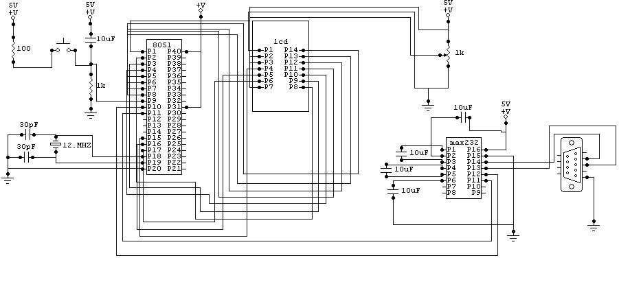
The moving message will be displayed on the LCD, which will be controlled through a microcontroller. The message will be sent by a computer using RS232. The circuit diagram of the moving message display is shown in this post,...
In various electronics-level adjustments, such as LED drivers for LCD panel backlight controls, the AD5228 can be utilized. A manually adjustable LED driver is illustrated. The AD5228 is a dual-channel, digitally controlled potentiometer (DCP) that can be employed in applications...

The SI4704 and SI4705 enhanced FM receivers are advanced portable solutions that offer embedded antenna support, digital audio output, worldwide FM band support, and flexible, mature FM functionality through a simple API. These receivers utilize Silicon Labs' tuned-resonance antenna...
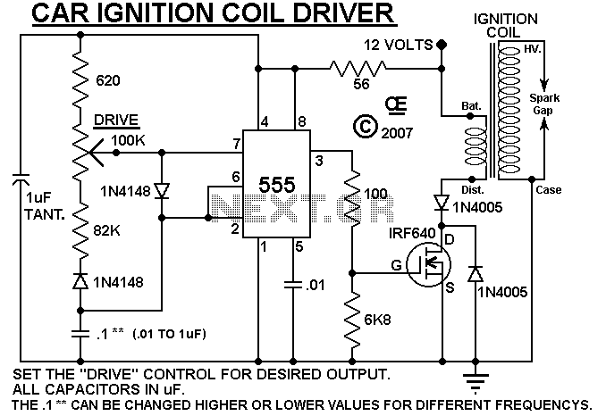
A simple design based on a 555 to drive a car ignition coil. This was designed for a small electric fence to protect a vegetable garden from small animals called marmots. Last year, they ate one of the crops...
The Atmel AT89C2051 keylogger circuit connects to a PC keyboard via a PS/2 connection cable, facilitating data transfer between the keyboard and the circuit during program execution. The Atmel AT89C2051 microcontroller is a popular choice for implementing keylogger circuits due...
The spectrometer vacuum chamber is constructed from 304-grade stainless steel, with the design executed by Vacuum Generators based on the work of Jones, Read, and Cvejanovic, detailed in T. Jones' Ph.D. thesis from the University of Manchester (1984). The...
Warning: include(partials/cookie-banner.php): Failed to open stream: Permission denied in /var/www/html/nextgr/view-circuit.php on line 713
Warning: include(): Failed opening 'partials/cookie-banner.php' for inclusion (include_path='.:/usr/share/php') in /var/www/html/nextgr/view-circuit.php on line 713