
Hardware
The vacuum chamber serves a critical role in the spectrometer system, ensuring that the interaction between the electron beam and the gas target occurs in an environment free from contaminants and external magnetic fields. The use of 304-grade stainless steel provides durability and resistance to corrosion, while the mu-metal lining effectively shields against magnetic interference, which is vital for maintaining the integrity of the measurements.
The pumping system, consisting of a turbo-molecular pump backed by a roughing pump, is designed to achieve low pressures efficiently. The specified pressure of better than 2.0E-8 torr indicates a high-quality vacuum, essential for experiments involving electron interactions, where any residual gas could affect the results.
The design of the flanges and feedthroughs allows for versatile configuration and adjustment of the experimental setup. The incorporation of rotary motion feedthroughs for the analysers and electron gun enables precise control over their positioning, facilitating a range of experimental geometries. The careful placement of the ionization gauge is crucial for minimizing noise, which could otherwise compromise the sensitivity of the photomultiplier tube.
The target gas delivery system is engineered for flexibility, allowing for different configurations depending on the experimental requirements. The use of stainless steel tubes and shielded PTFE hoses ensures that the gas delivery is not only efficient but also maintains the integrity of the vacuum environment.
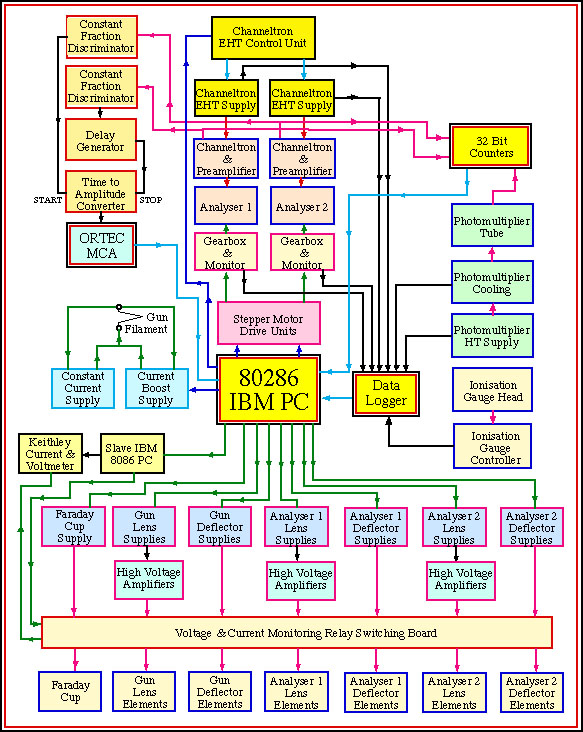
Overall, the design and construction of the vacuum chamber and associated systems reflect a high level of engineering, aimed at achieving optimal conditions for spectroscopic measurements in electron beam experiments. The attention to detail in materials, configuration, and operational parameters underscores the complexity and precision required in advanced experimental setups in the field of electron spectroscopy.The The spectrometer vacuum chamber (figure 1) is manufactured from 304 grade stainless steel, the construction being carried out by Vacuum Generators using a design of Jones, Read and Cvejanovic, full details of which may be found in T. Jones` Ph. D. thesis (University of Manchester (1984). Figure 1. The (e, 2e) Vacuum System (Simple view). The chamber is constructed of 304 grade non-magnetic stainless steel. The spectrometer hangs from the top flange, as detailed below. The chamber is pumped by a Balzers 500l/s Turbo-molecular pump, which is backed by a 16l/s Edwards low acoustic noise roughing pump. The Chamber is lined internally with 3mm thick mu-metal, and a mu-metal cylinder encloses the chamber externally as shown.
This reduces the magnetic field at the interaction region to less than 5mG, an acceptible level for the electron energies used in this experiment. 3mm thick mu-metal magnetic shielding is placed both internally and externally to decrease extraneous external magnetic fields to less than 5mG at the interaction region.
The system is pumped by a Balzers 500l/s turbo-molecular pump backed by an Edwards 16l/s roughing pump, and achieves a background working pressure better than 2. 0E-8 torr after 1 week of pumping while baking the system to a temperature of 90 °C. The top flange of the vacuum system is a 25mm stainless steel flange with 11 conflat CF70 flanges arranged around a central 200mm flange designed for locating a hydrogen source.
Three rotary motion feedthroughs allow the analysers and electron gun angles to be changed externally via stepper motors for both analysers and for the electron gun. The ionisation gauge is placed at right angles to the main flange to prevent light from the thoriated iridium filament entering the vacuum system, which would increase noise on the photomultiplier tube.
The ionisation gauge feedthrough is sooted, and a loose cover is placed over the entrance in the chamber flange to prevent stray light from the ion gauge entering the vacuum system. The target gas enters the system via a CF70 flange which has two 6mm stainless steel tubes welded into the flange.
One of these is internally connected to a gas jet which can be set at 45 ° to the incident electron beam and is used in the perpendicular plane experiments. The other gas feed is connected to a hypodermic needle set at 90 ° to the incident beam for measurements in other geometries.
These stainless steel feeder tubes are connected to the nozzle using grounded shielded PTFE hose. The gas jet which is not currently used in the interaction region can be used to non-locally fill the chamber with gas for background counting measurements. The final CF70 flange is used when the photomultiplier tube is cooled, usually during baking of the system following exposure to atmosphere.
This is necessary since the bi-alkali photocathode of the photomultiplier tube degrades rapidly at temperatures in excess of 55 °C, and baking of the vacuum system is most effective for temperatures closer to 90 °C (this is the maximum that can be obtained with the present heating tapes). Figure 2. The Spectrometer mounted from the Top Flange. The spectrometer is shown configured in the perpendicular plane, the electron gun being placed in the vertical position with respect to the analysers which span the horizontal detecion plane.
The electron gun is a two stage non-energy selected gun that produces an incident electron beam current of up to 4 microamps at an incident energy from around 30eV to 300eV. The analysers are identical, and consist of a 3-element electrostatic lens focussing the interaction region onto the entrance of a hemispherical electrostatic energy analyser.
The electrons selected in angle and energy are amplified using Mullard 919BL channel electron multipliers. The interaction region defined by the interaction of the gas target beam and the electron beam is focussed onto the
🔗 External reference
Related Circuits
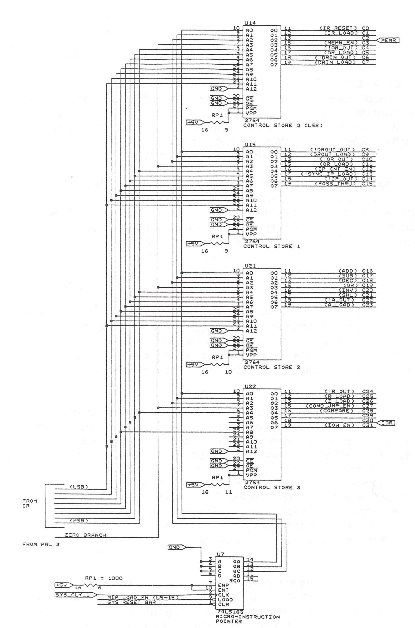
The datapath consists of registers, an ALU, and an internal system bus. Registers are fast memory locations internal to the CPU, distinct from main system memory, and serve as temporary storage during calculations. The ALU is a combinational logic...

The V2.2 PCB features four spare connectors (X11 to X14) that can be utilized for various inputs and outputs, as they are conveniently accessible on the 37-pin DB connector. Similarly, the V3.0 PCB includes four spare connectors (SPR1 to...
The Openbench Logic Sniffer is an open-source logic analyzer designed to support the SUMP logic analyzer software at minimal cost. Source and design files can be downloaded from the Gadget Factory project page. The project originated from discussions in...
This design was published in the June 1994 issue of Electronics Australia and has proven extremely popular. The kit was sold by Jaycar Electronics but has since been discontinued. It is a simple device that connects between your keyboard...

The 51 microcontroller features a full-duplex serial communication port, enabling straightforward serial communication between the microcontroller and a computer. However, certain conditions must be met for effective communication, such as the computer's serial port operating at RS232 levels while...
The microcontroller unit (MCU) will read images from the DataFlash memory via the SPI bus based on the known velocity. It will then send these images to the LED drivers using the SPI bus, controlling the on and off...
Warning: include(partials/cookie-banner.php): Failed to open stream: Permission denied in /var/www/html/nextgr/view-circuit.php on line 713
Warning: include(): Failed opening 'partials/cookie-banner.php' for inclusion (include_path='.:/usr/share/php') in /var/www/html/nextgr/view-circuit.php on line 713