
Door alarm circuit with a time of recognition NE555
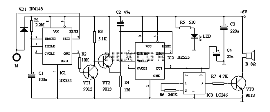
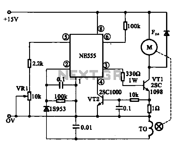
The door alarm circuit employs a 555 timer IC configured in monostable mode, which allows for a simple yet effective timing mechanism. The resistor R1 and capacitor C1 together determine the timing interval for the alarm system. The output of the 555 timer is responsible for controlling the state of the transistors VT1 and VT2, which manage the charging of capacitor C2 and the activation of the alarm sound circuit.
Transistor VT1 acts as a switch that, when activated, allows current to flow to the alarm circuit, while VT2 serves to short capacitor C2, preventing it from charging until the door is manipulated. The touchpad (M) provides a user interface that detects when the door is being opened. The alarm condition is triggered when the door remains open past the designated time limit, which is adjustable by changing the values of R1 and C1.
The integrated circuit IC3, which is the alarm sound generator, remains inactive until a high signal is received from IC2, indicating that the door has been left open for too long. The system's design incorporates safety measures to ensure that it operates effectively without posing a risk of electric shock, highlighting the importance of using appropriate power supply methods. This door alarm circuit is suitable for residential or commercial applications, providing an additional layer of security against unauthorized access.Door alarm here with a time recognition, the owner opened the door is normally open the door, open the door to complete the action within the general 30s, so it does not alarm, tried to open the door to strangers or thieves breaking open the door is not normal, usually a longer time, Once more than 30s, it will sound an alarm, it has great practical value.Circuit shown in Figure 1, mainly by the 555 IC alarm IC components.Timebase circuit IC1 and R1, C1 composition transient time T monoflop 4min around, usually IC1 at steady state, the pin output low, VT1 off, VT2 conduction, the capacitor C2 is shorted VT2 It can not be charged when the base circuit IC2 threshold terminal feet high, pin output low, the alarm sound integrated circuit IC3 does not work without power supply, speaker B silent.M is a touch pads, connected with a metal door. When someone unlocking Chung Ning apricot µ brain hard µ mother shouted shin Xiang and C1 trigger end feet, IC1 into the transient, pin output high, then the transistor conduction VT1, VT2 off, power can charging of C2 through R4, with the extension of the charging time, feet IC2 potential declining after about 30s, IC2 flip it feet high output, so IC3 electrical work alarm.
If the open time in less than 30s, then the IC2 pin is low, the circuit will not alarm. Alarm sound duration T1 determined by IC1 transient time, T1 1.1R1 C1 4min, 4min after, feet of IC1 output low, VT1 off, VT2 conduction, IC3 power failure, the alarm sound stops. If you touch door over 30s again, but again the alarm circuit.Battery power is available (four batteries in series) power supply, but must not use capacitor step-down power supply circuit to avoid electric shock!
Related Circuits
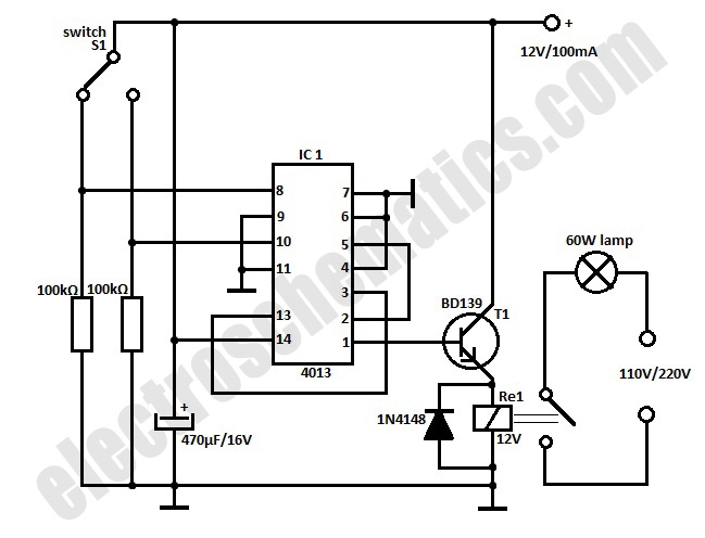
This automatic door light switch circuit activates a lamp when a door is opened and deactivates it when the door is closed again. The working principle of the circuit involves a sensor that detects the door's position. The automatic door...
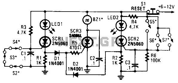
In this circuit, a low-powered silicon-controlled rectifier (SCR) is utilized to trigger a higher-powered SCR. When a switch is opened (S2, S3, S4) or closed (S5, S6, S7), either SCR1 or SCR2 is activated. This action subsequently triggers SCR3...
The current loop interface circuit diagram of the AD694 multi-functional sensor signal conditioner is utilized as a digital-to-analog converter (DAC). This current loop interface enables the conversion of digital values into voltage and subsequently into current signals. The circuit...
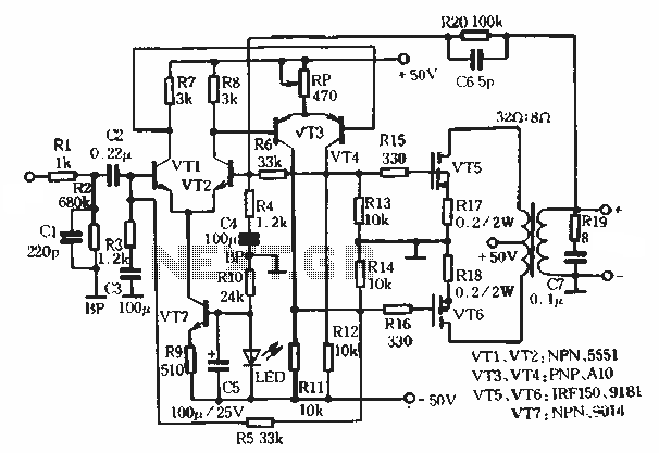
This article describes a transformer-based output FET amplifier, with tonal characteristics similar to those of tube amplifiers. It introduces various effects that are significant for audio enthusiasts. Power amplifier specifications include a rated output power of 50W (with an...
The Miniature DC Motor Speed Control circuit is designed to maintain a steady speed for micro motors, as illustrated in Figure 8-32. The circuit utilizes a voltage feedback mechanism suitable for applications such as tape recording machines that employ...
The following circuit illustrates a Boost Converter Circuit Diagram. This circuit is based on the 555 IC. Features: it only requires off-the-shelf components. The Boost Converter is a type of DC-DC converter that steps up the input voltage to a...