Multi-Zone Transistor-Based Intruder Alarm
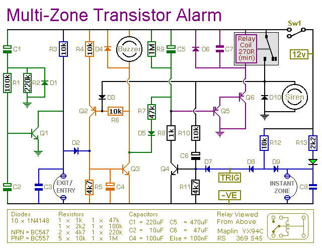
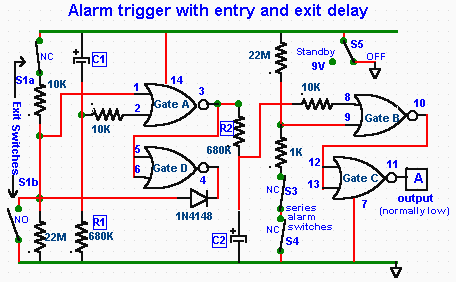
This is a simple transistor-based burglar alarm circuit. Its features include automatic exit and entry delays, along with a timed bell cut-off and reset. It is designed to be used with standard types of normally-closed input devices such as magnetic reed contacts, micro switches, foil tape, and passive infrared sensors (PIRs). The basic alarm consists of an "Exit/Entry" zone and an "Instant" zone, which is sufficient for many applications. However, larger buildings are best divided into multiple smaller zones. The design allows for the addition of as many zones as desired to the basic system. These are "Instant Zones" and can be triggered by both normally-open and normally-closed input devices. The system is user-friendly; when the green LED is lit, the alarm can be activated using switch SW1. The user has approximately 30 seconds to exit the building. Upon returning and opening the door, the buzzer will sound, providing another 30 seconds to deactivate the alarm. If the alarm is not turned off within this period, the siren will activate. The siren will continue to sound as long as at least one of the trigger switches remains open. However, if the trigger circuits are restored, the alarm will reset itself after about 10 minutes. The siren can be turned off at any time by switching off the alarm. Due to manufacturing tolerances, the exact duration of any delay depends on the characteristics of the components used in the circuit. However, by adjusting the values of resistors R2, R7, and R9, the exit, entry, and reset times can be modified to meet specific requirements. Increasing the resistor values will extend the time, while decreasing them will shorten it.
This transistor-based burglar alarm circuit employs a straightforward design that maximizes functionality while ensuring ease of use. The core of the circuit consists of a transistor acting as a switch, which is triggered by input devices that detect unauthorized access. The automatic exit and entry delays are essential for allowing users to leave or enter the premises without triggering the alarm unintentionally.
The circuit can be expanded to accommodate multiple zones, enabling coverage of larger areas by segmenting them into smaller, manageable sections. Each zone can be configured as an "Instant Zone," meaning that any activation will immediately trigger the alarm, offering heightened security. This flexibility is particularly advantageous for complex installations where different areas may require varying levels of surveillance.
The inclusion of a timed bell cut-off feature enhances the system's practicality, allowing for a predefined duration of alarm sound, after which it will automatically deactivate unless the alarm is reset. This feature is crucial in minimizing disturbances while still providing effective security.
The user interface is designed for simplicity. The green LED indicator serves as a visual confirmation that the system is armed. Once activated via switch SW1, the user is afforded a 30-second window to exit, which is indicated by the LED status. Upon returning, the buzzer alerts the user, ensuring they have time to disarm the system before the siren engages.
The circuit's reset functionality is critical for maintaining user convenience. If the alarm is triggered and the situation is resolved, the system can reset itself after a set period, reducing the need for manual intervention. This automatic reset feature is particularly beneficial in scenarios where multiple false alarms may occur.
The adjustment of resistor values (R2, R7, R9) allows for customization of the timing parameters according to the specific requirements of the installation. This adaptability ensures that the circuit can be fine-tuned to optimize performance based on the characteristics of the components used and the operational environment.
Overall, this burglar alarm circuit provides a robust solution for security needs, combining ease of use, flexibility in design, and effective alert mechanisms, making it suitable for a wide range of applications.This is a simple transistor-based burglar alarm circuit. Its features include automatic Exit and Entry delays - together with a timed Bell cut-off and Reset. It`s designed to be used with the usual types of normally-closed input devices such as - magnetic-reed contacts - micro switches - foil tape - and PIRs. The basic alarm has an "Exit/Entry" zo ne and an "Instant" zone. This will be adequate in many situations. However - larger buildings are best divided into a number of smaller zones. The design allows you to Add As Many Zones As You Like to the basic system. They are "Instant Zones" - and may be triggered by both normally-open and normally-closed input devices. It`s easy to use. Make sure that the green LED is lighting - then switch the alarm on using Sw1. You have about 30 seconds to leave the building. When you return and open the door - the Buzzer will sound. You have about 30 seconds to switch off the alarm. If you fail to do so - the Siren will sound. While at least one of the trigger switches remains open - the Siren will continue to sound. However - if the trigger circuits have been restored - the alarm will reset itself after about 10 minutes.
Of course - you can turn the Siren off at any time by switching off the alarm. Because of manufacturing tolerances - the precise length of any delay depends on the characteristics of the actual components you`ve used in your circuit. But - to some degree - by altering the values of R2, R7 & R9 you can adjust the Exit, Entry and Reset times to suit your requirements.
Increasing the values increases the time - and vice-versa. 🔗 External reference

