
Multicolor HD LED
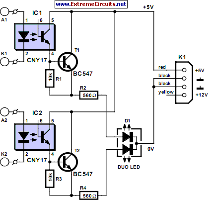
This circuit design enhances the functionality of hard disk activity indication in PC enclosures by integrating a multicolour LED that can signal activity from both IDE and SCSI drives. The use of optocouplers is crucial in this application, as they allow for electrical isolation between the drive signals and the LED, ensuring compatibility with different voltage levels. The Darlington transistor configuration amplifies the current to drive the multicolour LED effectively, while the series resistors are essential for current limiting and ensuring that each LED color operates within safe parameters.
When implementing this circuit, it is important to consider the characteristics of the specific multicolour LED being used, particularly its forward voltage and current ratings. The calculated series resistors for each LED segment should be adjusted to achieve uniform brightness across the colors. The option to utilize a +12-V power supply line provides flexibility in power management, particularly in systems where additional power sources may be limited.
The compact design of the circuit board is advantageous for installation in tight spaces within PC enclosures, and the use of hot-melt glue for securing the board enhances reliability. Overall, this circuit serves as a practical solution for improving hard disk activity indication in systems utilizing both IDE and SCSI interfaces, providing users with a clear visual representation of drive activity.Most PC enclosures provide only a single LED to indicate hard disk access, with the LED being connected to the motherboard via a two-pin connector. However, this LED only works with IDE drives, and if a SCSI disk controller is fitted, its activity will not be visibly noticeable.
This small circuit remedies that problem using a multicolour LED. The activity LED for the IDE interface is usually driven by a connected device via one or more open-collector stages. It illuminates if either of the two possible IDE drives is activated. The shared series resistor limits the current and also provides short-circuit protection. Even if the LED is shorted out due to faulty wiring, the current is restricted to a safe level. An obvious solution would be to have the IDE and SCSI disks drive a shared dual LED, but unfortunately the current flows from the positive supply line through a series resistor, the LED and a transistor to ground. The dual LED would thus have to have a common anode, but no such device exists. All known multicolor LEDs have a common cathode lead. That means they cannot be connected directly, but we`re not that easily defeated. Only a small additional circuit is needed to allow the LED to be driven by the different interfaces. In this circuit, each of the drive signals from the two controllers is fed to an optocoupler, which acts nearly the same as the original LED.
The somewhat lower voltage drop of the infrared LED results in a somewhat greater current, but there`s hardly any need to worry about overloading. The optocouplers eliminate the problems with the different voltages. On the output side, a Darlington transistor consisting of the photo-transistor and a BC547 drives the multicolour LED.
The 10-k resistor (whose value of is not critical) provides secure cut-off of the driver transistor. The base of the phototransistor in the CNY17 is left open. The series resistors for the individual LED elements are dimensioned using the standard formula. It may be necessary to adjust their values slightly, depending on the relative brightness levels. The circuit can also operated from the +12-V line of the power supply if the values of the series resistors for the LEDs are suitably modified. If necessary, a third optocoupler stage can be added to allow a three-colour LED (red, green and blue) to be driven.
The circuit board has been designed to be so small that the components can be fitted in a few minutes and everything can be suspended from the LED in the PC enclosure. A drop of hot-melt glue will prevent the circuit board from becoming dislodged due to vibration. The supply voltage reaches the circuit via a normal small drive connector, to make it easy to obtain the necessary plug.
Otherwise, you can also use ordinary solder pins. 🔗 External reference
Related Circuits
White LEDs have a rated current at a voltage drop of about 3.3 to 3.4 V. It is ideal to be powered from the battery voltage which is slightly larger. Then there is the best energy used. In this...
The yellow LEDs are on a small PCB, which are easy to remove. On the PCB there are 3 yellow LEDs and 4 diodes. Pictures of the PCB can be seen here: Top-side - Bottom-side. The schematic is as...
The project utilizes a 10 x 20 grid of RGB LEDs controlled by the myRIO. It is operated through a web interface on any device that supports WebSockets. Originally, the system was built using an Arduino, but the creator...
A Meanwell LED driver rated at 27V and 2300mA is available for use, intended to power two parallel strings of six LEDs each. The question arises whether to maintain the existing circuit with the same component values or to...

The LTC3453 is a synchronous buck-boost DC/DC converter optimized for driving up to 4 white LEDs at a combined current of up to 500mA from a single Li-Ion battery input. The regulator operates in either synchronous buck, synchronous boost,...

Do not let its extreme simplicity deceive you — this device is useful! Many have been made over the years, and some have even been given away as gifts. Yes, multimeter... A multimeter is an essential instrument in electronics, used...