
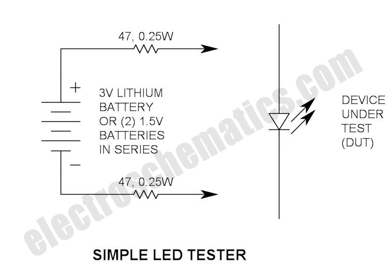
Simple LED Tester
A multimeter is an essential instrument in electronics, used for measuring voltage, current, and resistance. Its design typically includes a digital or analog display, a rotary switch for selecting measurement modes, and input jacks for connecting test leads. The device can measure direct current (DC) and alternating current (AC) voltage, making it versatile for various applications.
In a typical multimeter circuit, the core components include an analog-to-digital converter (ADC) for digital displays, operational amplifiers for signal conditioning, and resistors for current measurement. The rotary switch allows users to select different measurement functions, which connects the appropriate circuitry to the display. The test leads, usually color-coded red for positive and black for negative, connect to the circuit under test.
For enhanced functionality, some multimeters incorporate features such as continuity testing, diode testing, and temperature measurement. These additional capabilities are achieved through specialized circuitry and sensors. The inclusion of a microcontroller can further expand the device's features, allowing for data logging and advanced computations.
The simplicity of a multimeter belies its utility in both professional and hobbyist applications. It is a fundamental tool for troubleshooting electrical issues, verifying circuit functionality, and conducting experiments in electronics.Do not let its extreme simplicity deceive you — this thing is useful! I have made many over the years and have even given some away as gifts. Yes multimete.. 🔗 External reference
Related Circuits
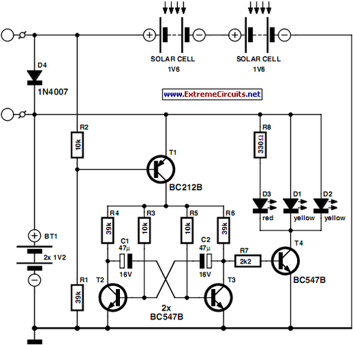
This circuit is designed as a warning flasher to alert road users to dangerous situations in low-light conditions. It can also function as a bicycle light, adhering to traffic regulations. White LEDs are recommended for use as a front...
The circuit below illustrates powering one or two LEDs from the 120-volt AC line using a capacitor to drop the voltage and a small resistor to limit the inrush current. Since the capacitor must pass current in both directions,...

The circuit utilizes a dual operational amplifier integrated circuit (IC), specifically the 1458, which contains two separate op-amps within a single package. In this configuration, the first op-amp functions as a voltage follower, directing its output to charge capacitor...
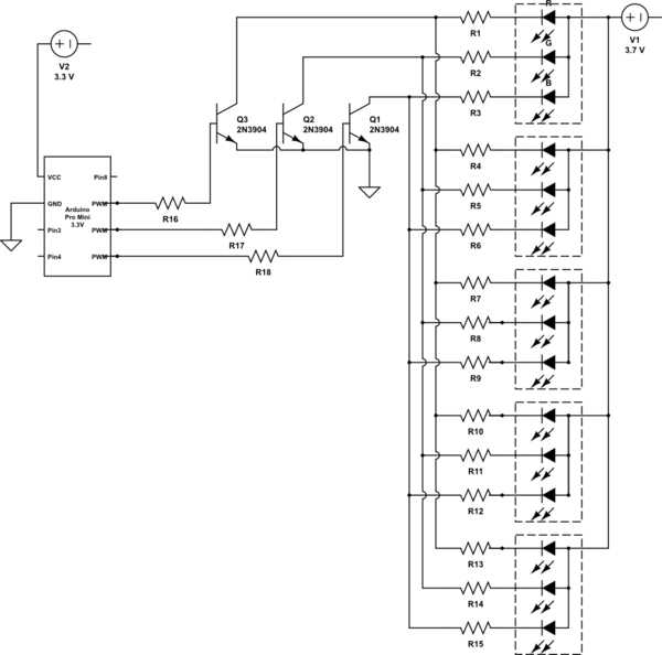
It is noted that the LEDs are not configured in parallel with the transistor. If they were, the LEDs would illuminate when the transistor is off. Instead, the LEDs are connected in parallel before entering the transistor. The transistor...
A low resistance (0.25 - 4 ohm) continuity tester for checking soldered joints and connections. This simple circuit uses a 741 op-amp in differential mode as a continuity tester. The voltage difference between the non-inverting and inverting inputs is...
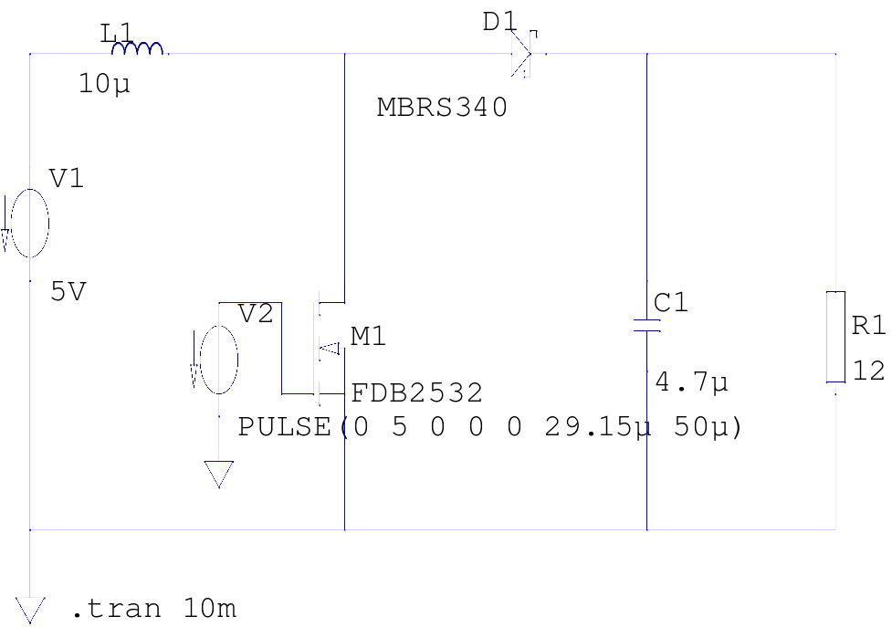
The supply voltage is 5V, and the goal is to increase it to 12V with a load current of 1A, resulting in an output power of 12W. A switching frequency of 20kHz has been selected, requiring a duty cycle...