
Multimedia RIAA Preamplifier
The preamplifier circuit described is essential for converting the low-level audio signals from a magnetic cartridge into a format suitable for digital conversion. The NE5532 operational amplifier is chosen for its low noise characteristics, which are critical in maintaining audio fidelity during the amplification process. The circuit must be designed to include RIAA correction, which is crucial for restoring the frequency response of the vinyl record to match that of standard audio playback. The input impedance of 47 kΩ is particularly important as it matches the output impedance of most magnetic cartridges, ensuring maximum power transfer and minimal signal loss.
The layout of the circuit should prioritize short signal paths and proper grounding techniques to reduce noise and interference. The use of shielded cables is recommended for the connections between the cartridge and the preamplifier to prevent electromagnetic interference. Additionally, the housing for the circuit should be constructed from metal to provide shielding from external noise sources, and it should be properly grounded to ensure a low-noise operation.
For the power supply options, the choice between a battery and a mains adapter should be made based on the user's needs and the potential for noise. The battery option provides the cleanest power source, ideal for audiophiles who prioritize sound quality. On the other hand, using a mains adapter can simplify the setup but requires careful consideration of potential noise filtering techniques to maintain audio integrity.
In summary, the design and implementation of the preamplifier circuit for converting vinyl to CD require careful attention to components, grounding, and shielding to ensure high-quality audio reproduction. The integration of RIAA correction and the choice of power supply will significantly influence the performance of the system, making it essential to consider these factors during the design phase.Even if a large number of album titles once available on vinyl are now, little by little, being proposed as CDs, not all are available and far from it. You may have treasures in your collection that you would like to burn on CDs. First, preserving a CD is easier than preserving a vinyl record, and second, we have to admit that turntables are disap
pearing, even on fully-equipped Hi-Fi systems. From a point of view of software and PCs, converting from vinyl to CD is not a problem. A large number of programs, whether paid for freeware, are available to re-master vinyl records with varying degrees of success and to eliminate pops, crackles and other undesirable noises. All of these programs work with the sound card of your PC and that, admittedly, is where the problem starts.
Most high-quality turntables are equipped with a magnetic cartridge which typically delivers just a few mV. The cartridge signal requires a correction of a specific frequency, called RIAA correction. If our older readers will perfectly recall what RIAA is all about, others from the CD generation may not know what the acronym RIAA stands for, guessing it may have something to do with illegal downloading of music on the Internet.
For mechanical reasons related to the vinyl engraving procedure, high-boost frequency correction is carried out while respecting a very precise curve defined a long time ago by the RIAA (Recording Industry Association of America) and, which therefore, quite naturally, was baptized RIAA correction. Reversing the correction is the role of to the preamplifier for the magnetic cartridge. Since this correction boosts the lowest frequencies, such a preamplifier is very sensitive to all undesirable noises, hums, including, of course, the one coming from the 50-Hz (or 60-Hz) mains power supply.
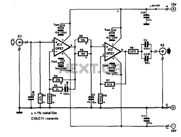
It is important to take that into account while making this project which must be done carefully with respect to grounding and shielding. The schematic of our preamplifier is very simple because it uses a very low-noise dual operational amplifier.
Here the NE5532 is used, whose response curve is modelled by R7, R8, C8, and C9 (or R14, R15, C13, and C14 respectively) in order to match the RIAA correction as closely as possible. The input has an impedance of 47 kR, which is the standardized value of magnetic cartridges, and its 1, 000-Hz gain is 35 dB which allows it to supply an output level of a few hundred mV typically required by for the line input of a PC sound cards.
The connection between the cartridge and the input of the amplifier requires shielded wiring to avoid the hum problems discussed above. Likewise we recommend fitting the assembly in a metal housing connected to the electric ground. With respect to the power supply, three solutions are proposed: If you are a purist and you want to rule out any noise whatsoever, you will utilize a simple 9-V battery.
Then, the components outlined with a dotted line will not be useful. Since the circuit only uses a few mA, such a solution is acceptable unless your collection of vinyls is impressive. If you desire a more elegant technical solution that might sometimes cause more undesirable noise on the signals, you may want to wire up the components within in the dotted lines and you can steal the 12 V positive voltage available from your PC.
A Y-connector inserted on the power supply of one of the internal drives or peripherals will work very well for that. Finally, you may also use a mains adapter set to 12 V and connect it to the +12-volt point of the drawing in order to benefit from additional filtering, which is not a luxury for some.
🔗 External reference
Related Circuits
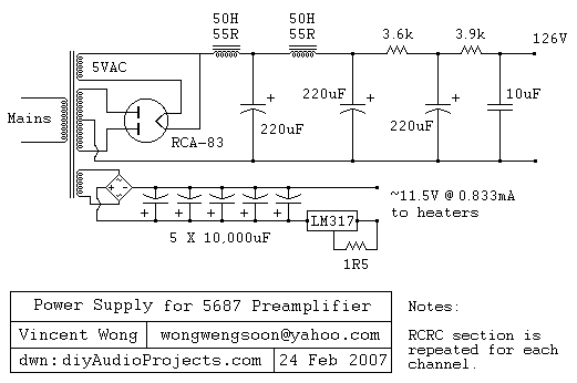
The RCA-83 rectifier utilizes 5VAC for the filament supply. The heaters for the 5687 tubes are powered by a full bridge rectifier consisting of MUR860 diodes, followed by five 10,000µF Elna capacitors. Current regulation is achieved through an LM317...
Since the volume control is after the gain stage, the preamp can be easily overloaded. I tried to limit the input signal by mounting a 470 k resistor in series with the CD input. A voltage divider is formed...
This preamplifier is a requirement resulting from many friends to provide a high-quality preamplifier, capable of driving high-quality power amplifiers with good sound. It is not, however, difficult to make; it combines simplicity and handiness. It does not allocate...
A fundamental component for audio applications, this circuit functions as a general-purpose preamplifier. It is recommended to utilize two circuits for stereo configurations. This audio preamplifier circuit is designed to amplify low-level audio signals, making it suitable for a variety...
The circuit utilizes two 2N3819 FETs arranged in a cascode configuration. The lower FET functions in common source mode, while the upper FET operates in common gate mode, achieving full high-frequency gain. The lower FET is adjustable, enabling tuning...
This amplifier is designed to be integrated with preamplifiers that lack a phono input. A phono input is essential for standard record players equipped with dynamic pick-ups, which remain widely used. The amplifier not only elevates the output of...
Warning: include(partials/cookie-banner.php): Failed to open stream: Permission denied in /var/www/html/nextgr/view-circuit.php on line 713
Warning: include(): Failed opening 'partials/cookie-banner.php' for inclusion (include_path='.:/usr/share/php') in /var/www/html/nextgr/view-circuit.php on line 713