
Stereo Preamplifier Circuit

This audio preamplifier circuit is designed to amplify low-level audio signals, making it suitable for a variety of audio applications. The circuit typically consists of a transistor or operational amplifier (op-amp) configuration that increases the amplitude of the input signal while maintaining signal integrity.
In a typical implementation, the circuit may include input capacitors to block DC offset and protect the following stages from unwanted voltage levels. The gain of the amplifier can be adjusted using feedback resistors, allowing for flexibility in signal amplification based on the requirements of the application.
For stereo applications, two identical circuits can be employed, one for the left audio channel and another for the right. This ensures that both channels are amplified equally, providing a balanced audio output. The circuits can be powered using a dual power supply to accommodate the operational needs of the op-amps or transistors, ensuring optimal performance.
Additional components such as potentiometers may be included to allow for volume control, and bypass capacitors can be added to filter out noise and improve overall sound quality. Proper grounding and layout considerations are crucial to minimize interference and ensure that the audio signal remains clean and undistorted.
Overall, this preamplifier circuit serves as a vital building block in audio systems, facilitating the enhancement of sound quality and enabling the connection of various audio sources to amplifiers or mixers. A building block for audio work, the circuit can be used as a general-purpose preamp. Use two circuits for stereo applications.
Related Circuits
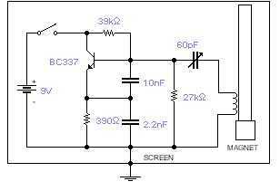
This basic oscillator will detect the Earth magnetic field. The ferrite rod and coil are taken from an old Medium Wave receiver and a small magnet is glued at one end. Tune to a medium wave commercial station until...
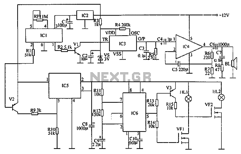
The circuit functions as a danger zone warning system incorporating a regulator circuit, a pyroelectric infrared detection trigger circuit, an electronic switching circuit, and audio circuits. The regulator circuit includes a three-terminal regulator integrated circuit (IC2), a resistor (R3),...
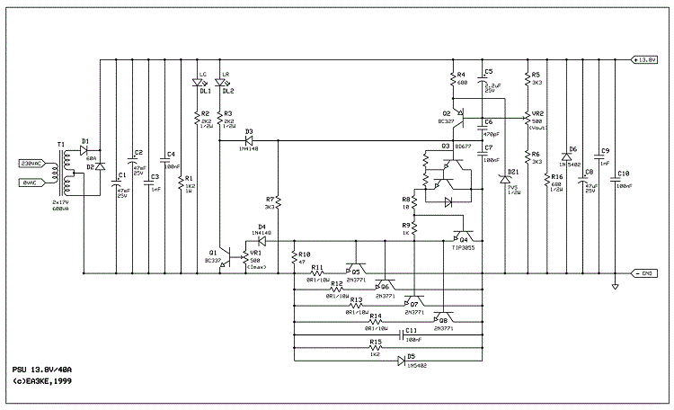
This power supply is designed for amateur use and has been operational for over 10 years. Its design is straightforward and largely resistant to radio frequency interference (RF). The system incorporates various components, with the most significant being a...
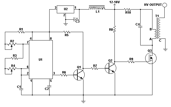
This solid-state Tesla Coil design is similar to the two-transistor version available on this site, utilizing a standard flyback transformer to generate high voltage output. Unlike the previous design, it employs a 555 timer to effectively drive a single...

A flashing LED indicates the need to water a plant in a 3V powered circuit. This circuit is designed to signal when a plant requires water. A LED flashes at a specified interval. This circuit operates on a 3V power...
Individuals seeking a distinctive gift for Christmas and New Year may find this project appealing. Certification of this project will undoubtedly create a preference for it. The project in question appears to be a creative endeavor aimed at providing a...