
MULTIPLEXED CLOCK DlSPLAY

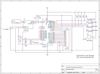
The circuit described is a digital clock display system utilizing multiplexing techniques to manage LED output effectively. The core of the design is based on TTL (Transistor-Transistor Logic) counters, which are employed to count pulses generated by a stable 60-Hz oscillator. This frequency corresponds to the standard timing for seconds in a minute, ensuring accurate timekeeping.
At the heart of the counting mechanism is a series of flip-flops, specifically designed to handle the transitions between different time states. Flip-flop M plays a crucial role by being set on every cycle once the counter reaches the designated hour mark. This flip-flop acts as a control signal that indicates the transition from one hour to the next.
Gate G3 is implemented to monitor the output of the counters. It is configured to recognize the specific condition when the count reaches 13:00 (or 1:00 PM in a 12-hour format). Upon detection of this condition, Gate G3 sends a signal to clear the contents of the shift register, effectively resetting the seconds and minutes while preparing the system for the next hour.
Additionally, the carry flip-flop is essential for ensuring that the hour digit increments correctly. When the time transitions from 12:59:59 to 1:00, the carry flip-flop remains set, which allows a binary '1' to be loaded into the hours digit. This mechanism ensures seamless transitions in the display, maintaining the integrity of the time representation.
Overall, this multiplexed display circuit is a robust solution for digital clock applications, providing accurate time display while minimizing the complexity of the circuitry through the use of TTL technology and efficient counting mechanisms.Multiplexed display suitable for LED readouts is provided by circuit using TTL counters to count 60-Hz Iine.When count reaches o`clock, flip-flop M is set on evely cycle. Gate G3 then detects when time goes to 13 o`clock, and clears shift register.Carry flip-flop remains set, so 1 is loaded into hours digit to accomplish transition from 12:59:59 to 1:0..
🔗 External reference
Related Circuits
The DS1307 is a hardware real-time clock that operates using the I2C protocol. It features improved graphics with a traditional alphanumeric LCD (model HD44780). Icons indicate the status of the Alarm ON/OFF state, enhancing the visual appeal of the...
This is a voltage controller oscillator that was designed as a wide range oscillator to generate clock pulses for a stepper motor drive system. It does however have some interesting features. The original application used a stepper motor for...
This is a programmable clock timer circuit that uses individual LEDs to indicate hours and minutes. 12 LEDs can be arranged in a circle to represent the 12 hours of a clock face and an additional 12 LEDs can...
This circuit converts the ripple from a wall wart supply to a clean Line x 2 digital clock. Doing it this way eliminates the need to put AC into the unit, which then has to be rectified and filtered...
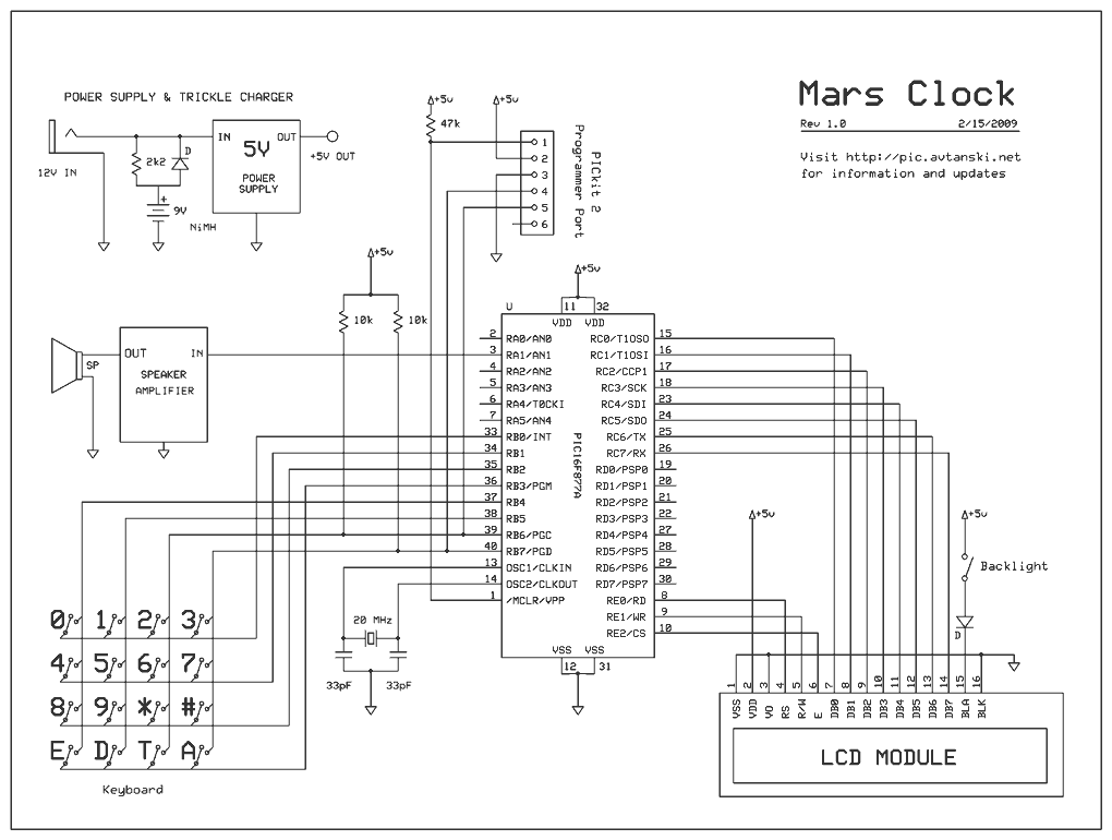
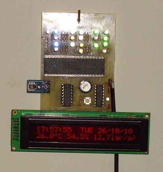
It has 16 timers that can be independently paused and restarted, and can run forward or backward. There are 16 alarms with configurable sounds and actions. Timers can show Earth, Mars, Jupiter, etc. times at the same time. How...
I use a RealTimeClock Maxim DS1305. The RTC backup power is a supercapacitor (0.22F). I test it for 4 weeks, works fine. For this reason it doesn't have the capability to change the time, but you can do small...