
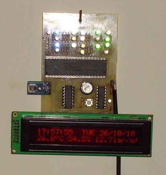
Digital clock with thermometer and hygrometer
The described system incorporates a Maxim DS1305 Real-Time Clock (RTC) and a Sensirion SHT11 digital temperature and humidity sensor, creating a robust timekeeping and environmental monitoring solution. The RTC is powered by a 0.22F supercapacitor, ensuring backup power during outages and capable of retaining time settings for at least 28 days. The operation of the RTC is controlled through specific programming sequences that enable setting the time and configuring the control registers for optimal functionality.
In terms of functionality, the RTC allows for minor adjustments to the seconds value, which is executed via a button press that sets the seconds to 30 without affecting other time units. The programming process requires two stages: the initial setup without a specific line to redirect execution and a subsequent reprogramming that incorporates this line, effectively halting the execution of certain routines after the initial configuration.
Daylight Saving Time adjustments are managed through dedicated routines, ensuring the clock accurately reflects the time changes that occur twice a year. The system is designed to operate in a 12-hour mode for user interface elements while providing a 24-hour format for display purposes.
The Sensirion SHT11 sensor is integrated on a printed circuit board (PCB) with necessary components such as pull-up resistors and decoupling capacitors already in place, facilitating straightforward implementation. The sensor performs temperature and humidity measurements at regular intervals, specifically every 10 seconds. Temperature readings are taken at the start of each minute (00, 20, and 40 seconds), while humidity measurements occur at 10, 30, and 50 seconds. The system calculates both Absolute Humidity and Relative Humidity, with dedicated routines for each measurement and calculation process.
The routines are organized into specific lines of code, ensuring clarity and ease of reference during programming and debugging. The temperature measurement and calculation routines are distinctly separated, allowing for streamlined data processing and accurate environmental monitoring. Overall, this system exemplifies an efficient integration of timekeeping and climate measurement technologies, suitable for various applications requiring precise temporal and environmental data.I use a RealTimeClock Maxim DS1305. The RTC backup power is a supercapacitor (0,22F). I test it for 4 weeks, works fine. For this reason it don't have the capability to change the time, but you can do small-corrections. Once you push the button, the seconds change to 30, with no effect to minutes, hours etc. The routine is in lines 1878-1887 "sec30". You set the time when you program the PIC. You have to program two times. The first time without line 91 (goto rdtime). The routines setDS and settime is execute. SetDS is setting RTC's control and trickle charger registers. In the settime routine, you set the time. After this, you add line 91 (goto rdtime) and you reprogram it. Now the routines do not execute. RTC can keep the setting and time at least for 28 days. The routines DST3 and DST10 are for DaySavingTime. The check register is flag, 1. The checking routine is in lines 434-460. In the last Sunday of March, the 02:00 o'clock became 03:00 o'clock. In the last Sunday of October, the 02:00 o'clock became 01:00 o'clock. I set the RTC for 12H mode, leds for 12H and display for 24H. I use a digital humidity and temperature sensor Sensirion SHT11. I bought it in a PCB, with the pull-up resistor and decoupled capacitor ready in place. Measurements make every 10 seconds. At 00, 20 and 40 seconds it measures the temperature and calculate the temperature and Absolutely Humidity ("gr/m3" grams at cubic meter of air). At 10, 30 and 50 second it measures the humidity and calculate the Relative Humidity (%). The check register is flag, 0. The checking routine is in lines 464-475. The measure temperature routine is in lines 477-514 "measTEMP" and lines 625-714 "measure". The calculate temperature routine is in lines 1793-1820 "calcTEMP". The measure Relative humidity routine is in lines 560-590 "measRH" and lines 625-714 "measure". The measure Absolute humidity routine is in lines 515-555 "measAH". The calculate Relative humidity routine is in lines 717-1470 "calcRH". The calculate Absolute humidity routine is in lines 1473-1728 "calcAH". 🔗 External reference
Related Circuits
This project outlines a digital clock featuring an alarm function, utilizing a PIC16F877 microcontroller to achieve an accurate 1-second delay with Timer0 through Roman's zero error method. The time is displayed in large font on a 4G—20 character LCD,...
This circuit incorporates a datasheet-compliant trigger signal, reversed polarity protection, an optional test button, and the capability for battery operation. It utilizes either the U1 L601E3 or MAC97A8 triac, rated for 400 V and 1 A. When U1 is...
This circuit was designed for digital cameras, which are known to have significant power consumption. For instance, the Minolta E223 camera requires approximately 800 mA. In practice, this demand can be met using a mains power supply or high-capacity...
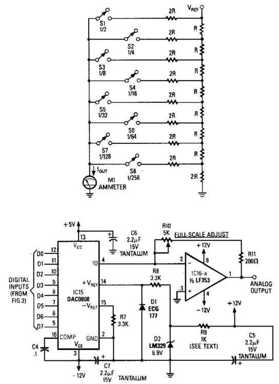
Figure A illustrates an R/2R resistor ladder. Each closed switch increases the current output. A basic channel A/D converter is depicted in Figure B. The voltage reference (D2) is shared among all channels, while the value of the dropping...
28 LED Clock Timer Circuit. This is a programmable clock timer circuit that uses individual LEDs to indicate hours and minutes. Twelve LEDs can be arranged in a circle to represent the 12 hours of a clock face, along with...
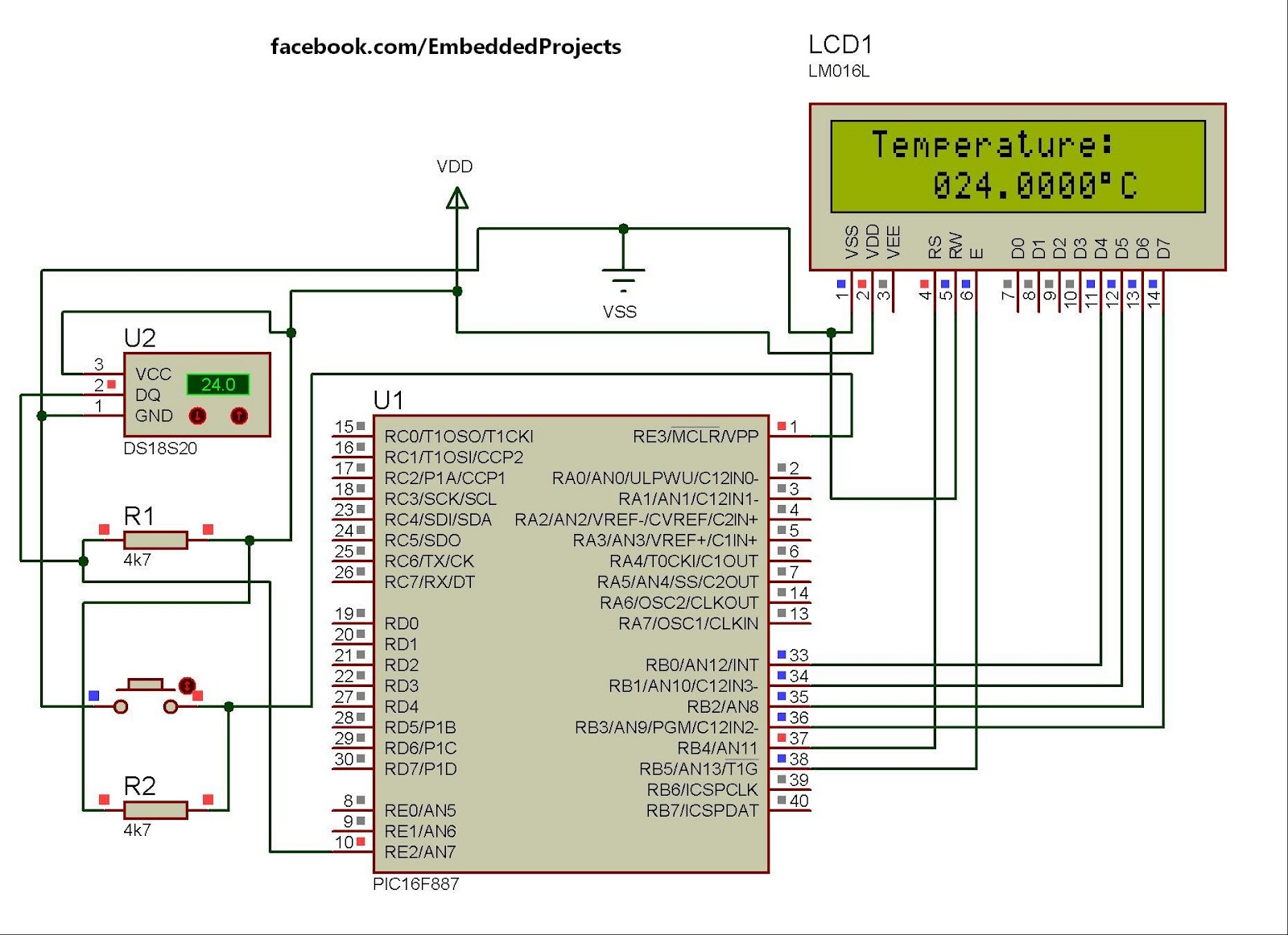
The hardware configuration for utilizing multiple 1-Wire temperature sensors, such as the DS1820, is straightforward. Communication between the microcontroller and the temperature sensors occurs over a single-wire bus. Additionally, it is possible to power the devices directly through this...
Warning: include(partials/cookie-banner.php): Failed to open stream: Permission denied in /var/www/html/nextgr/view-circuit.php on line 713
Warning: include(): Failed opening 'partials/cookie-banner.php' for inclusion (include_path='.:/usr/share/php') in /var/www/html/nextgr/view-circuit.php on line 713