
battery charger regulator

The described circuit functions as a battery management system designed to prevent overcharging, thereby enhancing battery longevity and performance. The high-current MOSFET serves as the primary switch in the charging path, allowing for efficient control of the current flowing into the battery. When the battery voltage approaches the set threshold, the MOSFET is turned off, effectively ceasing the charging process and protecting the battery from potential damage due to overvoltage.
The 3-terminal regulator, REG1, is crucial for providing a stable voltage to the control circuit, ensuring that the MOSFET operates reliably. The choice of an 8V output from REG1 suggests that the circuit is designed to operate within a specific range, optimizing performance while minimizing energy loss.
In practice, the circuit may include additional components such as resistors for voltage sensing, capacitors for filtering, and possibly a microcontroller for more advanced control features. The integration of these components allows for fine-tuning of the charging parameters, enabling the system to adapt to varying battery conditions and charge states.
Overall, this add-on circuit represents an effective solution for extending the life of car batteries by preventing overcharging, making it a valuable addition to standard battery charging practices.Most off-the-shelf car battery chargers cannot not be left connected to the battery for long periods of time as over-charging and consequent battery damage will occur. This add-on circuit is placed in series with the battery being charged and is powered by the battery itself.
In effect, the circuit uses a high-current Mosfet to control the charging current and it turns off when the battery voltage reaches a preset threshold. Power for the circuit is fed from the battery to 3-terminal regulator REG1 which provides 8V.. 🔗 External reference
Related Circuits
This circuit can replace the single current-limiting resistor commonly found in inexpensive battery chargers. The alternative presented here will prove beneficial as it prevents the premature disposal of NiCd batteries after approximately three months of inadequate charging. The circuit...
There are many circuits for low voltage regulators. For higher voltages, such as supplies for valve circuits, the situation is different. Low voltage regulators are widely utilized in electronic circuits to provide a stable output voltage from a varying input...
Lead acid battery charger schematic using IC LM317. This lead acid battery charger circuit is simple to build and can be fit in a small box. The lead acid battery charger circuit utilizing the LM317 integrated circuit (IC) is a...
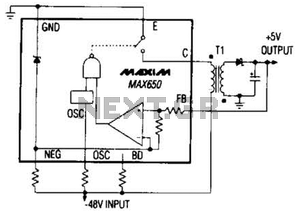
The Max650 switching regulator generates a regulated 5 V output from large negative voltages, such as the -48 V commonly found on telephone lines. This power supply requires several external components, including a transformer, and is capable of delivering...
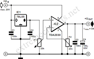
By combining a standard 78L05 voltage regulator with an integrated audio amplifier, specifically the TDA2030, it is possible to construct a simple yet effective adjustable voltage regulator. This regulator can output a voltage adjustable up to 20 V and...
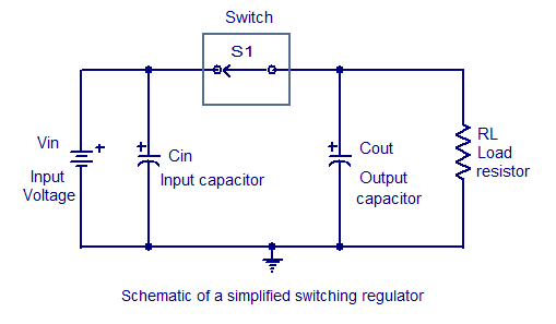
Switching regulators operate by drawing small amounts of energy from the input source and transferring it incrementally to the output. This is achieved using an electronic switch, which functions at a predetermined frequency, acting as a gate between the...