
Automatic street light circuit
The circuit utilizes a Light Dependent Resistor (LDR) as the primary sensor for detecting ambient light levels. The LDR is a variable resistor that changes its resistance based on the intensity of light it receives; it has low resistance in bright light and high resistance in darkness. This property is fundamental to the operation of the circuit.
When the ambient light level is high (daytime), the LDR’s low resistance keeps the base of the PNP transistor Q1 at a higher voltage than its emitter, thus keeping Q1 in the OFF state. As a result, Q2, which is connected to the emitter of Q1, also remains OFF, preventing current from flowing through the TRIAC, which means the lamp remains OFF.
As the sun sets and the light level decreases, the resistance of the LDR increases. This change allows the base-emitter junction of Q1 to become forward-biased, turning Q1 ON. Consequently, Q2 also turns ON, allowing current to flow through the TRIAC. The TRIAC then completes the circuit, enabling the lamp to turn ON.
The sensitivity of the circuit can be adjusted using R1, which is in series with the LDR. By changing the resistance of R1, the threshold light level at which the circuit switches from OFF to ON can be fine-tuned. Additionally, R2 can be adjusted to further refine the sensitivity and responsiveness of the circuit to changing light conditions.
This design is particularly useful for automatic lighting systems, such as garden lights or street lights, where the control of illumination based on natural light levels is desired. The combination of transistors and a TRIAC provides a robust mechanism for controlling higher power loads, such as incandescent or LED lamps, while ensuring that the circuit operates efficiently and reliably.Below shown circuit will be automatically switched ON and OFF during night and morning times respectively. In above circuit R1 can be used to adjust the sensitivity. And the working of the circuit is very simple. The LDR will have very low resistance during day time so the transistor Q1 will be in OFF condition. And during night time the resistance will be very high so automatically the transistor Q1 will be ON. The Q1 is PNP transistor and the emitter of Q1 is given to base of Q2. So the Q2 transistor will be ON only if the transistor Q1 is ON. The TRIAC is used in the circuit to make is circuit complete. As the TRIAC will allow voltage to pass from either directions only when there is a certain threshold voltage in gate terminal. And the gate of TRIAC is controlled by transistor Q2. So totally the lamp will be ON during night time and will be again switched off during day light. To change the sensitivity of the circuit to light adjust R2. 🔗 External reference
Related Circuits

The LED indicator in this project can be used for bike indicators or car direction indicators. A 555 timer and a BCD 7490 are utilized along with several resistors, exceeding 100 in total across various electronic projects. The circuit employs...

CMOS and PMOS cross interface circuit with PMOS integrated circuit providing high input impedance, allowing the input current to be negligible. The CMOS and PMOS interface circuit is illustrated in the accompanying figure. The CMOS and PMOS cross interface circuit...

The ultrasonic drilling machine is essential machinery in the dairy industry for processing jewelry, primarily for natural stones, crystal agate, jade, and glass products. This machine is particularly effective for high-hardness materials, enabling both drilling and engraving. The following...
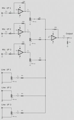
The microphone inputs are amplified approximately 100 times or 40 dB, with the total gain of the mixer, including the summing amplifier, reaching 46 dB. The microphone input is designed for microphones that produce an output of around 2...

This simple receiver AF amplifier can supply several hundred milliwatts to an 8-ohm speaker. The gain is approximately 200X. If high gain is not required, C2 can be removed, resulting in a gain of 20. R1 and C6 are...
This circuit was adapted from the Toggle Switch Debounced Pushbutton by John Lundgren. It is useful where the load needs to be switched on from one location and switched off from another. Any number of momentary (N/O) switches or...
Warning: include(partials/cookie-banner.php): Failed to open stream: Permission denied in /var/www/html/nextgr/view-circuit.php on line 713
Warning: include(): Failed opening 'partials/cookie-banner.php' for inclusion (include_path='.:/usr/share/php') in /var/www/html/nextgr/view-circuit.php on line 713