
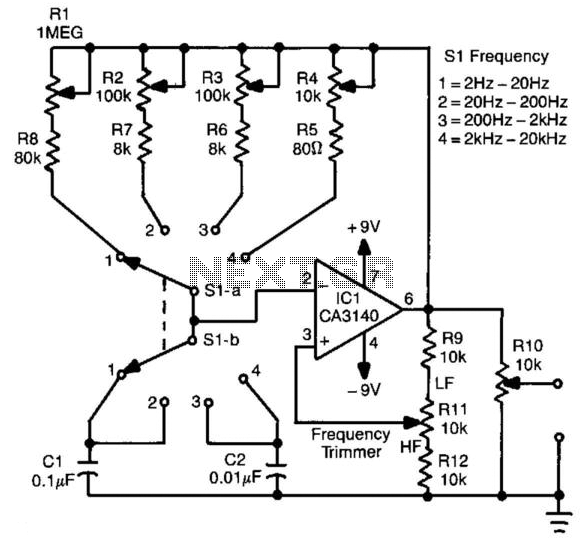
4-Decade Square-Wave Generator
The circuit is designed to produce a square wave output, which is essential for various applications such as signal testing, waveform generation, and clock pulses in digital circuits. The operational amplifier operates in a feedback loop configuration, allowing it to oscillate and produce the desired frequency output. The relaxation oscillator relies on the charging and discharging of capacitors, which are not explicitly mentioned but are typically integral to such designs.
The calibration controls, R1 to R4, allow for fine-tuning of the frequency ranges, ensuring precise adjustments can be made based on application needs. The frequency selection switches S1-a and S1-b facilitate easy user interaction, enabling quick changes to the desired frequency range without the need for complex adjustments.
Output level adjustment through R10 is crucial for applications requiring specific voltage levels, ensuring compatibility with downstream circuitry. The output characteristics of approximately 15 V peak-to-peak are suitable for driving various loads or for interfacing with other electronic components.
In summary, this circuit provides a versatile solution for generating square wave signals across a wide frequency range, with user-friendly calibration and output level adjustment features, making it suitable for a variety of electronic applications. This circuit will generate a square wave of 2 Hz to 20 kHz. The circuit uses an op amp in a relaxation-oscil lator configuration. The output is about 15 Vpp. Rl through R4 are calibration controls for each of the four frequency ranges, as selected by SI-a and Sl-b. RIO adjusts the output level. S1 Frequency 1= 2Hz - 20Hz 2= 20Hz-200Hz 3= 200Hz - 2kHz 4= 2kHz-20kHz 🔗 External reference
Related Circuits
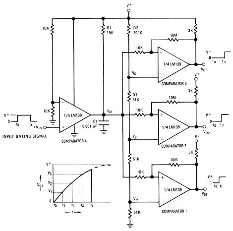
A measure delay generator, also identified similarly to a sequence generator, is a device that provides output signals at specified time intervals from a time reference. It automatically resets when the input signal returns to ground. The schematic illustrates...
The circuit is straightforward, utilizing a single IC chip, the ICL8038 function generator chip, which produces simultaneous sine, square, and sawtooth waveforms. The circuit consists of a minimal number of components, including two resistors, one transistor, five trimpots, and...
Stepper motors are a recurring topic of interest. This circuit converts a clock signal from a square wave generator into signals that have a 90-degree phase difference, which are necessary for driving the stepper motor windings. The trade-off for...

This is a simple circuit utilizing the NE555 integrated circuit (IC) designed to generate metronomes. Such a circuit is particularly beneficial for music learners. The configuration operates as an astable multivibrator centered around the NE555. The output frequency is...
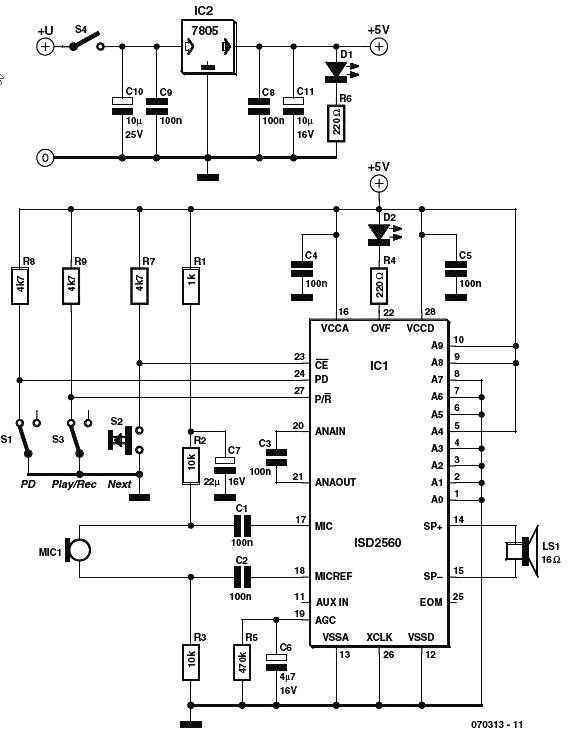
The voice generator scheme schematic diagram utilizes the ISD2500 series of chip-coders from Winbond, which encompasses all necessary components for recording and playback of voice messages. These chips feature microphone preamps with Automatic Gain Control (AGC), allowing compatibility with...
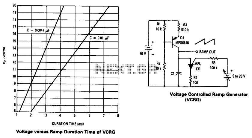
The current source created by Q1 in combination with capacitor C1 determines the duration of the ramp. As the positive DC voltage at the gate varies, the peak point firing voltage of the Programmable Unidirectional Thyristor (PUT) is altered,...