
Astable Multivibrator
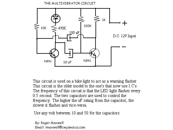
In the described circuit, a 470-ohm resistor is used in series with an LED in the collector circuit of transistor T1. This configuration is critical for ensuring proper current flow through the LED, which provides visual feedback regarding the operation of the transistor. The selection of a 470-ohm resistor, as opposed to a 470k-ohm resistor, is essential for maintaining adequate current levels to illuminate the LED without exceeding its rated specifications.
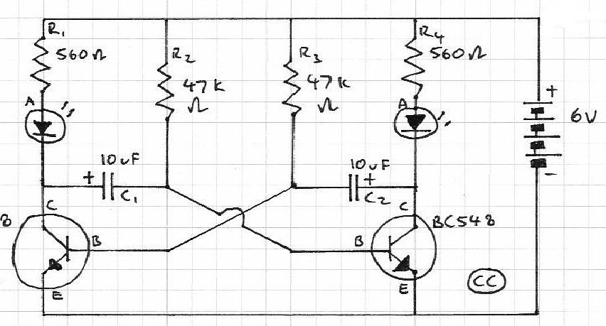
When integrating a 24V-3W bulb into the circuit, the operating resistance of the bulb must be taken into account. The bulb's resistance when lit is approximately 190 ohms, calculated using the formula \( R = \frac{V^2}{P} \), where V is the voltage (24V) and P is the power (3W). In a non-lit state, the resistance drops significantly to about 19 ohms, resulting in a potential collector current of approximately 1.3A when powered from a 24V supply. This high current level necessitates careful selection of transistors that can handle the increased load without overheating or failing.
Replacing resistors with lamps in the collector circuits of transistors introduces additional complexities. Not only must the resistor values be adjusted, but the overall circuit design must also accommodate changes in frequency and duty cycle of the driving waveform. The frequency of operation may affect the thermal performance and electrical characteristics of the transistors, as well as the response time of the lamps. Therefore, it is crucial to analyze the entire circuit to ensure compatibility and reliability when making these modifications. Proper simulation and testing should be conducted to validate the circuit's performance under the expected operational conditions.The resistor in series with the LED in Collector circuit of transistor T1 must be 470 ohm, not 470k. To connect the bulb 24V-3W, you should know that resistance of this bulb when lighting is 24x24/3 = 190 ohm, when it is not lit, the resistance is about 10 times smaller, e. g. about 19 ohm, so the collector current of the transistor may go up to 24V/19ohm = 1. 3A - need to pay attentions when choosing transistors. The lamps will be connected in collector circuits of transistors, replacing the resistors. However, it is not simple replace the resistors wiht the lamps, you have to change values of other components, as well as adjust for frequency and duty cycle of the wave. 🔗 External reference
Related Circuits
This unique and simple multivibrator circuit comprises only five components and operates without vacuum tubes or semiconductors, utilizing two miniature NE2 type neon lamps. It is best suited for interfacing with high-impedance circuits, such as those involving vacuum tubes...
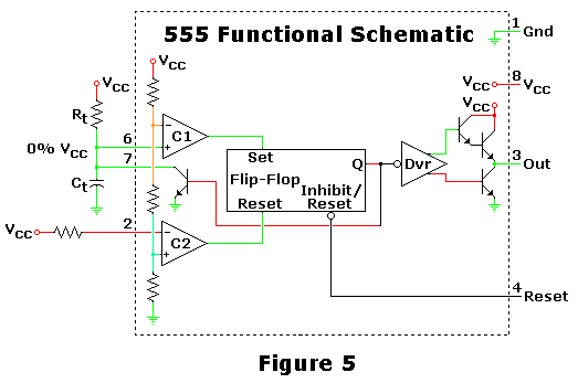
This is one of the most basic 555 circuits. This circuit is part of the chip's datasheet, complete with the math needed to design to specification, and is one of the reasons a 555 is referred to as a...

The circuit utilizes a CMOS dual D flip-flop (CD4013) to toggle a relay or other load using a momentary push button. Multiple push buttons can be connected in parallel to control the relay from different locations. A high signal...
Blinks 2 LEDs in sequence. An explanation of its operation is requested. It is understood that a capacitor charges, causing the LED to turn off, and when it discharges, the LED turns on. However, clarification on the purpose of...
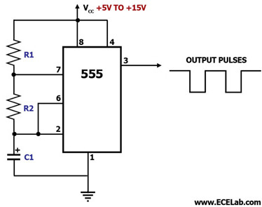
This circuit diagram illustrates the configuration of a 555 timer integrated circuit (IC) as an astable multivibrator. An astable multivibrator is a timing circuit characterized by unstable 'low' and 'high' states. Consequently, the output of an astable multivibrator continuously...
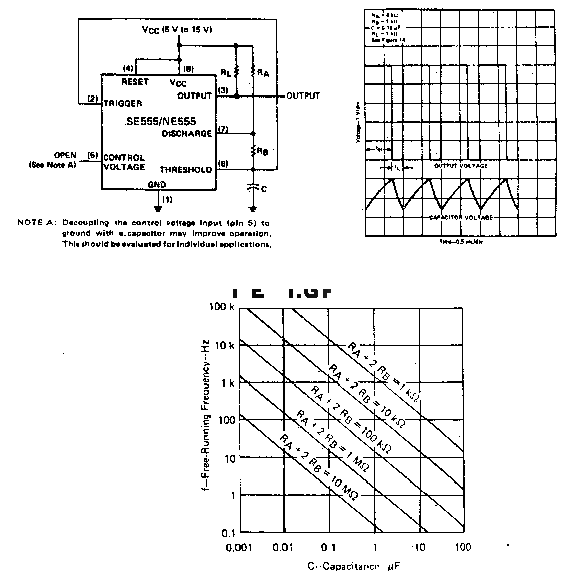
The capacitor C will charge through resistors Ra and Rb, and then discharge through resistor Rb only. The duty cycle may be controlled by the values of Ra and Rb. In this circuit configuration, a capacitor (C) is utilized to...