
Muscular Bio stimulator
The circuit design described involves a key switch (SW1) that is crucial for managing voltage levels to ensure patient safety during operation. By connecting SW1 to potentiometer P1, the circuit minimizes the risk of voltage peaks, which can be harmful. The alternative use of a standalone single-pole single-throw (SPST) switch is permissible, provided that the operator is diligent in setting P1 to its minimum position before powering the device.
In configurations with multiple output electrodes, the retention of the specified circuit components (IC1, R1, R2, C1, C2, SW1, and B1) is essential for maintaining functionality. The flexibility to duplicate other components such as P1, R3, R4, D1, D2, Q2, and T1 allows for scalability in device design, accommodating varying numbers of electrodes based on the application requirements.
The additional potentiometers and series resistors (R3) must be arranged in parallel to ensure that the circuit maintains consistent performance across all outputs. These components should be connected from the emitter of transistor Q1 to the positive power supply, ensuring that the circuit operates within the desired voltage range.
For applications requiring timed operation, the integration of a timing mechanism is advisable. The available circuits, such as the Timed Beeper, Bedside Lamp Timer, or Jogging Timer, can be adapted for use in this design. Adjustments to the timing components will be necessary to align with the operational needs of the specific application, ensuring that the timing function is both effective and reliable.SW1 should be ganged to P1 to avoid abrupt voltage peaks on the "patient`s" body at switch-on, but a stand alone SPST switch works quite well, provided you remember to set P1 knob fully counter-clockwise at switch-on. Some commercial sets have four, six or eight output electrodes. To obtain this you can retain the part of the circuit comprising IC1, R1, R2, C1, C2, SW1 and B1. Other parts in the diagram (i. e. P1, R3, R4, D1, D2, Q2 & T1) can be doubled, trebled or quadrupled. Added potentiometers and R3 series resistors must be wired in parallel and all connected from Emitter of Q1 to positive supply. Commercial sets have frequently a built-in 30 minutes timer. For this purpose you can use the Timed Beeper the Bedside Lamp Timer or the Jogging Timer circuits available in this Website, adjusting the timing components to suit your needs
🔗 External reference
Related Circuits
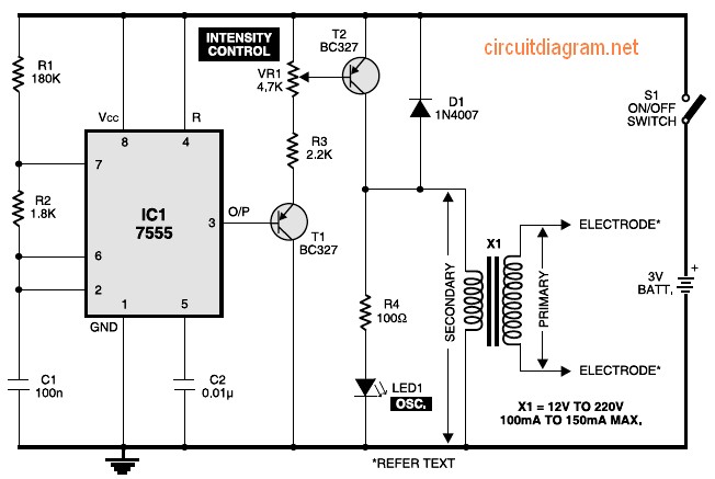
Figure 1 shows the circuit of a muscular stimulator. The IC 7555 is configured as an astable multivibrator to generate approximately 80Hz pulses. The output from IC1 is connected to transistor T1, whose emitter is linked to the base...
In spite of the improvement of communication link and despite all progress in advanced communication technologies, there are still very few functioning commercial wireless monitoring systems, which are most off-line, and there are still a number of issues to...
The current generated flows through clips placed on the earlobes. The output current is adjustable from 80 to 600 microamperes, following the recent launch in Europe. The described device utilizes a current generation mechanism that delivers a controlled microcurrent through...

Due to the recent launch of Cranial Electrotherapy Stimulation (CES) portable devices in Europe, a similar circuit has been designed for hobbyists. CES is a widely used method for electrically enhancing brain function and has been prescribed by medical...
A Transcutaneous Electrical Nerve Stimulation (TENS) device is essentially a machine designed to deliver electric stimulation to the nerves. This device was prescribed to the author. A Transcutaneous Electrical Nerve Stimulation (TENS) device is a therapeutic apparatus utilized for pain...
There is substantial evidence suggesting that certain forms of communication and energy exist beyond the traditional electromagnetic spectrum, of which we may have exemplary instances. The exploration of communications and energies beyond the conventional electromagnetic spectrum involves understanding various phenomena...
Warning: include(partials/cookie-banner.php): Failed to open stream: Permission denied in /var/www/html/nextgr/view-circuit.php on line 713
Warning: include(): Failed opening 'partials/cookie-banner.php' for inclusion (include_path='.:/usr/share/php') in /var/www/html/nextgr/view-circuit.php on line 713