
Muscular stimulator circuit
The following diagram illustrates a telephone amplifier circuit built around the small amplifier IC LM386. This simple telephone amplifier does not require an external power supply, as it draws power directly from the telephone line. The amplifier is capable of delivering a reasonably good volume.
Additionally, an inverter circuit can be employed to power electric razors, stroboscopes, flash tubes, and small fluorescent lamps using a 12-volt car battery. Unlike conventional feedback oscillator inverters, the oscillator in this design is separate from the output stage, allowing for easy adjustment of the oscillator frequency.
A solar-powered circuit can provide a pure regulated 5V DC output. This circuit consists of an oscillator transistor and a regulator transistor. The solar panel charges the battery when sufficient sunlight generates a voltage above 1.9V, necessitating a diode between the panel and the battery for proper operation.
This low-power inverter utilizes only nine components to convert 10 to 16V DC into 115V at 60Hz square wave power, suitable for operating AC equipment up to 25W. The first section of the 555 timer is configured as an astable oscillator, with resistors R2 and capacitor C1 determining the frequency, with the output available at pin 5.
Furthermore, a doorbell circuit featuring flashing LEDs enhances the visual appeal of the circuit. Here, IC1 (NE555) functions as a clock generator, set up as an astable multivibrator with a frequency adjustable via potentiometer VR1. The clock pulses generated by IC1 are provided to the subsequent components.
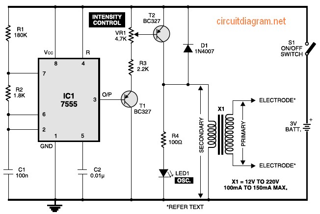
This comprehensive overview highlights the functionalities and configurations of various electronic circuits, demonstrating their applications in muscle stimulation, audio amplification, power inversion, and solar energy utilization. Each circuit employs specific components and configurations to achieve desired outcomes, showcasing the versatility and practicality of electronic design in everyday applications.Figure 1 exhibits the circuit with the muscular stimulator. IC 7555 is actually wired just as one astable multivibrator to build about 80Hz pulses. The particular output involving IC1 is fed to be able to transistor T1, whose emitter is actually further connected to the starting of transistor T2 via R3 as well as VR1. The enthusiast of transistor T2 is connected to one end of the secondary turning of transformer X1. The opposite end on the secondary winding from the transformer is connected to ground. Here`s a circuit which stimulates nerves of the part of your body exactly where electrodes are generally attached. It is useful to help remedy headache along with muscular discomfort and bring back frozen muscles that impair movement.
Though it offers muscles stimulation and invigoration, it`s mostly an aid in removing cellulitis. The device comprises 2. The following diagram is the circuit diagram of telephone amplifier, build based small amplifier IC LM386. This is a easy build telephone amplifier There is no extra electrical power supply required to power up the telephone amplifier circuit, as it draws power from the telephone line itself.
The amplifier will supply fairly very good volume. This inverter circuit can be used to power electric razors, stroboscopes and flash tubes, and small fluorescent lamps from a 12 volt car battery. In contrast to the usual feedback oscillator type of inverter, the oscillator of this inverter is separate from the output stage, which allows easy adjustment of the oscillator frequency to suit.
Powered with solar panel, the circuit will give you 5V pure regulated DC voltage. The circuit is made up of an oscillator transistor as well as a regulator transistor. The solar panel charges the battery when sunlight is bright enough to generate a voltage above 1. 9v. A diode is necessary between the panel and also. This low power inverter uses only 9 parts and turns 10 to 16VDC into 115V / 60Hz square wave power to operate AC equipment up to 25W. The first section of the 555 timer is wires as an astable oscillator with R2 and C1 setting the frequency.
The output is available at pin 5. The. This is the door bell circuit with flashing LEDs to make the circuit more attractive. IC1 (NE555) is applied right here as being a clock generator. It is actually set up as an astable multivibrator whose frequency could be altered using the support of potensiometer VR1. The clock pulses received from IC1 are fed to. 🔗 External reference
Related Circuits
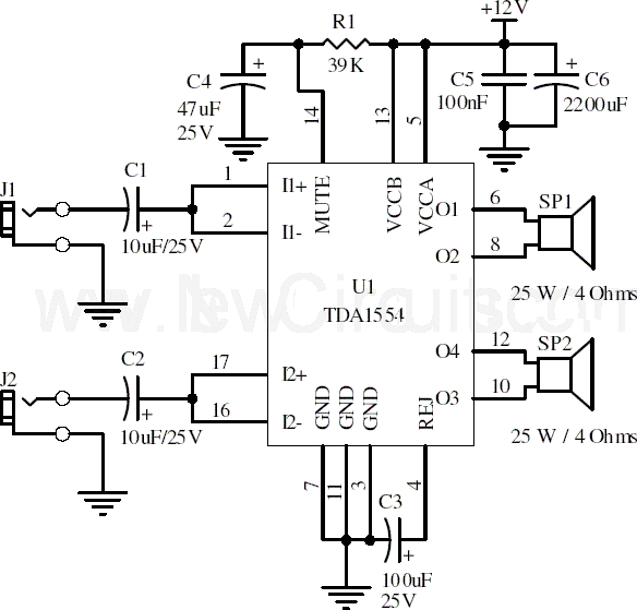
This document presents a 22-watt stereo audio power amplifier circuit diagram utilizing the TDA1554 integrated circuit from NXP Semiconductors (formerly known as PHILIPS Semiconductors). The circuit is designed to amplify stereo signals effectively. It dissipates approximately 28 watts of...
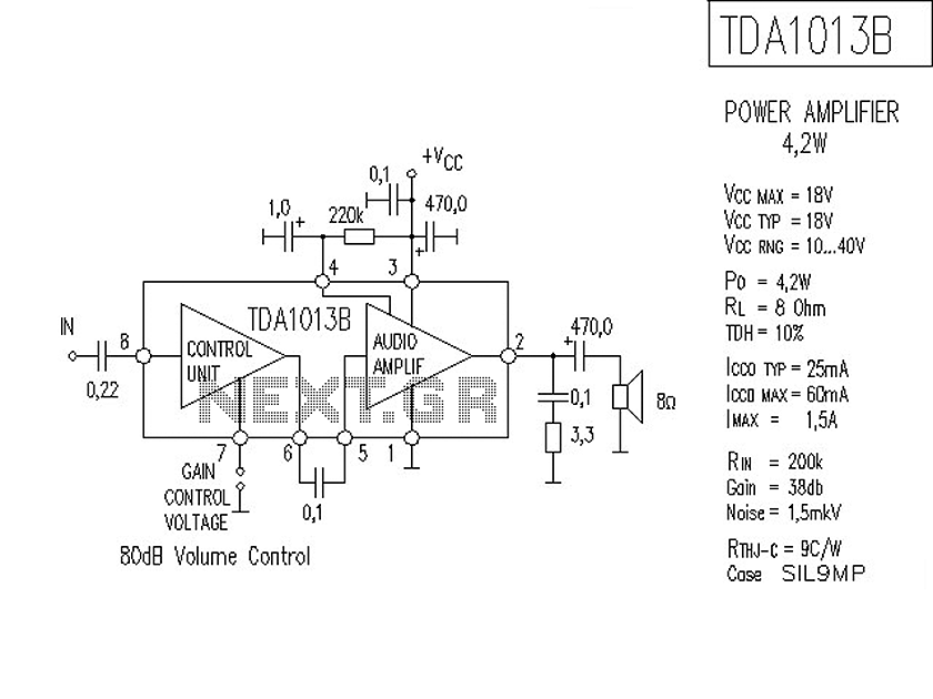
The following is a circuit for a 4-watt audio amplifier. The amplifier utilizes an integrated audio amplifier chip, TDA1013B, which is capable of delivering an audio power output of up to 4W at an 8-ohm load. Its wide supply...
The back EMF voltage spikes produced by stepper motors, especially higher voltage motors, can damage a PC's printer port if connections are made incorrectly, flyback diodes are absent, or connected in reverse. The safest options are opto-isolated or buffered/inverted...
An FM transmitter, commonly referred to as an FM transmitter, utilizes two transistors, specifically the 2N2222 model. When in operation, this FM transmitter requires a 9-volt battery for power and operates with an antenna that is less than 12...

A simple white LED driver schematic can be created using the EL7513 constant current boost regulator, which is specifically designed for driving white LEDs. This driver can manage 4 LEDs in series or up to 12 LEDs in a...
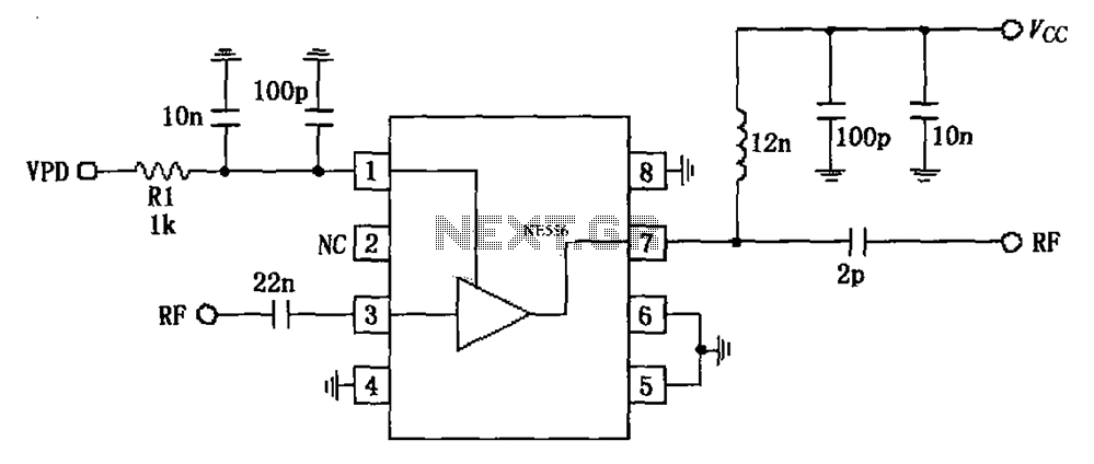
The circuit is based on an 880 MHz RF2347 low noise amplifier application. The radio frequency (RF) signal enters through input pin 3, and after amplification, the output is available at pin 7. The amplifier is directly coupled to...