
musical continuity
The continuity tester circuit employs a simple yet effective design that integrates a single transistor as a switch, allowing for both visual (LED) and audible (musical output) feedback. The transistor's base is connected to a resistor that limits the current, ensuring that the transistor operates within its safe limits while maintaining sensitivity. The LED serves as a visual indicator of continuity, illuminating when a conductive path is established. The incorporation of a musical greeting card circuit adds an engaging auditory element, making the tester more interactive.
The choice of components, such as the piezo speaker and the flexibility of the banana sockets, enhances the circuit's usability in various applications, from educational demonstrations to practical testing in moist environments. The design is versatile enough to accommodate different LED colors based on the power supply used, allowing for customization depending on user preference or specific application requirements.
In educational settings, the circuit serves as an excellent tool to illustrate fundamental concepts of electrical circuits, such as closed loops and series connections. The interactive nature of the activity fosters engagement and enhances understanding among participants. Furthermore, the circuit's adaptability for use as a game adds an element of fun, making learning about electrical principles more enjoyable. Overall, the continuity tester circuit is a practical and effective tool for both educational and practical applications in electronics.A continuity tester is handy for checking that there is an electrical conducting path between two points. The following circuit has the advantage that it is very sensitive and it gives both a visual and audible indication of continuity.
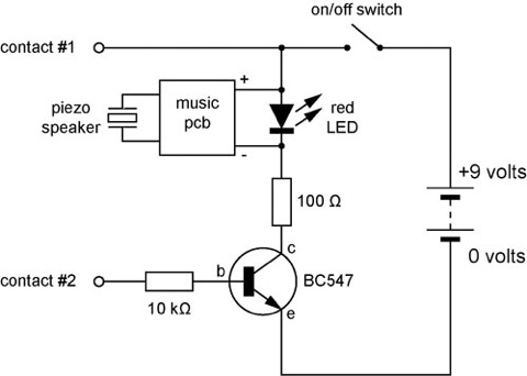
An audible tester is handy since you are normally looking at where you are placing the tester contacts rather th an looking at the tester itself. The circuit diagram shows that the continuity tester is made up of a sensitive one-transistor switch which turns on both a LED and a circuit taken from a musical greeting card. Most greeting card circuits are powered by a single 1. 5 volt "hearing aid" cell so I have connectedthe music printed circuit board (pcb) across the red LED which maintains a fairly constant voltage of about 1.
5 volts across it. Some musical circuits use two cells so you could change the LED to a green, blue or white one which would increase the voltage across the pcb. The base resistor value is not critical. I have specified 10 k © here but its purpose really is only to limit the maximum current that can pass through the base-emitter part of the transistor.
A value of 100 k © seems to work just as well. Again the collector resistor (100 ©) is not too critical. Higher values will limit the current through the music pcb and LED making the music quieter and slower. The music`s pitch may may also be affected a little. Two musical greeting card printed circuit boards (pcbs) and their piezo speakers are shown in the picture alongside.
The one on the left is unmodified and has its cell, cell holder and off/on switch still attached. These have been removed from the pcb on the right. This next photo shows the components soldered together. The contacts used here are connected to 4 mm "banana" sockets. This makes the circuit more versatile since a range of probes or connectors can be attached to the sockets. Below are two views of the finished musical continuity tester in its box. The piezo speaker leads were unsoldered from the pcb and fed through two small holes drilled into the box before being soldered back onto the pcb.
The red LED is glued to the box and attached by flying leads to the pcb. The banana sockets are attached on either side of the box. As a moisture tester. This circuit is sensitive enough to operate when the two contacts are placed in damp soil or on a damp wall. Your skin is moist enough to trigger the circuit - see the next use. To demonstrate to students that components need to be connected in a closed loop for a circuit to work.
Get a class of students to form a circle and hold hands. Get two adjacent volunteers - one to hold the tester in such a way that their index finger touches one socket/contact. The other volunteer touches just the other socket/contact (making sure not to touch the first volunteer).
Once all are holding hands the music plays and I point to various partners to momentarily break from holding hands - the music stops and then resumes when they hold hands again. I also make sure the students realise they are "connected" together in a series circuit. As the base circuit for a game of skill like "operation". A wiggly length of rigid wire (florist`s wire or a bent coat hanger) is connected to one socket. A small wire loop is attached to the other socket using a flexible wire lead. The aim of the game is to move the loop along the wiggly wire without touching it and setting off the music.
🔗 External reference
Related Circuits

The main point is that a connection will either be made or it will not; there is no middle ground. A solder joint will connect or it will not connect. The resistance range of 0.25 to 4 ohms raises...
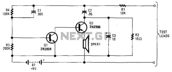
A continuity tester equipped with an audible indicator can be more beneficial in certain situations than one with a visual indicator, as it allows the user to maintain focus on the task without diverting attention. Transistors Q1 and Q2...
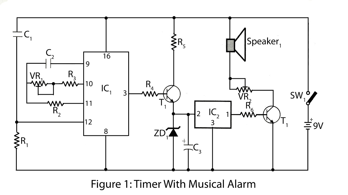
The timer with a musical alarm is an electronic timer project utilizing the CD4060 integrated circuit. It provides a delay ranging from 1 minute to 2 hours. The circuit diagram for the timer with a musical alarm is part...

A simple musical light chaser circuit diagram and schematic using IC CD4016. This circuit blinks lights in response to sound, audio, or music output, causing 10 lights to dance according to sound frequency. The musical light chaser circuit utilizing the...
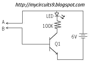
This circuit offers an advantage over traditional continuity testing devices, which typically utilize a multimeter to assess circuit continuity. Multimeters are not suitable for testing high impedance or resistance circuits, such as transformers, capacitors, and high-value resistors. This circuit...
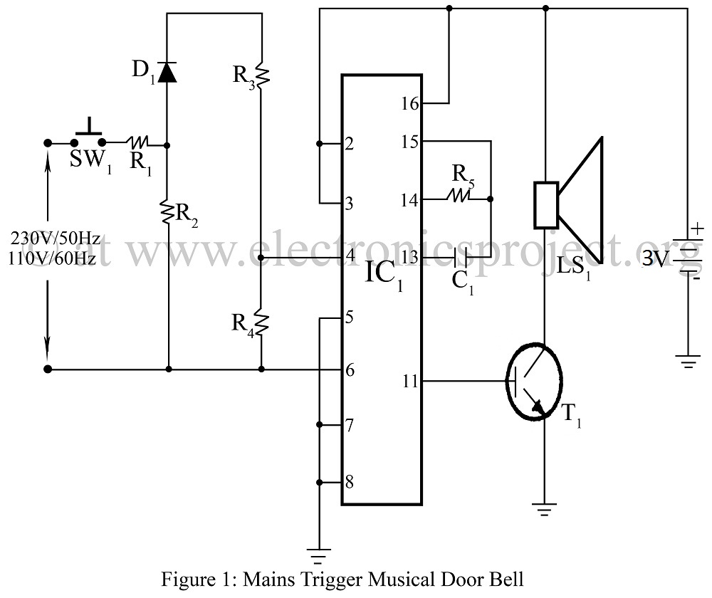
Mains-triggered musical doorbell using the musical IC UM3482 circuit diagram, featuring various and unique doorbell projects. The mains-triggered musical doorbell circuit utilizes the UM3482 integrated circuit, which is specifically designed for generating musical tones. This circuit is activated by a...