
Continuity or just plain connect
The circuit described involves a basic operational amplifier (op-amp) configuration using the 741 op-amp model. The op-amp serves as a signal amplifier that takes a weak input signal and boosts it, allowing for greater control and sensitivity in the circuit's response. The circuit is designed to detect the presence of a short circuit by measuring the voltage across two points. When the resistance is very low, indicative of a short, the output of the op-amp switches states, allowing an LED indicator to light up.
In this configuration, the op-amp's non-inverting input (V+) is connected through a resistor to the circuit under test, while the inverting input (V-) is held at a reference voltage. The resistor value determines the sensitivity of the circuit; a low resistance will bring V+ closer to V- and activate the output. The potentiometer in the circuit allows for fine-tuning of this threshold, providing flexibility in adjusting the sensitivity to differentiate between normal operation and a short circuit.
Power for the op-amp is derived from an external source, ensuring that it can amplify the input signal effectively. This setup is crucial for applications where the integrity of the circuit needs to be monitored continuously, such as in automotive or industrial environments where intermittent faults can lead to significant operational issues.
The operational amplifier's functionality is further enhanced by its ability to decouple the circuit under test from the power supply, preventing potential interference from the power source that could affect the measurement accuracy. This decoupling is essential for ensuring that the op-amp operates solely based on the signal from the circuit being tested, thereby providing reliable feedback on circuit conditions.
In summary, the described circuit effectively employs an operational amplifier to detect short circuits by measuring voltage levels and utilizing LED indicators for visual feedback. The careful selection of components and configuration allows for precise monitoring of circuit integrity, which is critical in various electronic applications.The point being if it connects it`s good if it don`t it don`t, there`s no inbetween. If you got a solder joint it`s going to connect or it`s not going to connect, that`s it. 0. 25 to 4ohms come on really. Do they even make resistors that small to set it with For a intermitent break well you know what those are like. I had one in/before my starter once, total pain. So there`s a farmer story for ya, and where`s the buzz Just got a multimeter, the battery that was in it was 6. 1v don`t know if that`s not enough. I put in 9. 76v and still no buzz. thx So we find out were going to "short" for a "short" That`s right, a very low resistance is equivalent to a "short" or just a wire connecting the leads.
ya because were looking for a "short", makes perfect sense, don`t you think I thought electronics was crazy when i seen the same symbol for 3 totally different parts. Now i know why all the nerds in high school looked so confused. So the beeper/buzzer still doesn`t work, well everything else does so it`s not a total loss. So the continuity vs the connection is going by by, the "short" is where it`s at. The two circuits you displayed are not functionally equivalent. One (the COMPLEX one) has an Op Amp (741) in it, and the other does not. With the op-amp, in order for the LED to light it accepts power from the circuit under test, in order to slew the op-amp so the LED turns on.
Hey Boba, I smell something fishy, that would make perfect sence if there wasn`t any power on the complex one. How do you hook the two powers together How`s it going to read "just" the power from the circuit I really don`t know much about op-amps, but I do know that they have additional power supply leads.
They are amplifiers, meaning you use them to generate a strong signal from a weak one while retaining its properties of interest (usually you want to preserve the shape of the signal while multiplying its voltage amplitude, someone might want to correct me here). So you need additional power to generate a stronger swing. You have the same thing going in a guitar amplifier: the signal from the guitar comes from one circuit that contains guitar pick-ups.
Additional power comes from the wall plug, AC, rectified and filtered to DC internally, then made to follow the signal from the sensor circuitry. I`ve seen more op-amp schematics that draw power from the primary circuit, though, which is also fine if you don`t need more than, say, 5V or 12V or so.
In this case, however, voltage is not an issue; op-amp is used to decouple the circuit under test from the additional power source (battery), as BobaMosfet vividly explained :) Would anyone like to comment on this Also, I tried to read the schematic FJC posted, and I guess that it works by driving op-amp`s V+ input slightly above V- (via 10ohm resistor), which gives high output and LEDs don`t light up, unless 10R is shorted, in which case V+ <= V- (that potentiometer in the middle is used to trim this sensitivity threshold ), output goes low and LEDs light. Does this make any sense Comment#1 If your going to buy one of their Mutimeters A830 A930, Don`t, because i don`t know who makes it because the manual is in Chinese.
I had to google it just to find out how to use it, hence the original q. Comment#2 All that matters to me now is that this no name mutimeter also came with a dead battery and it DOES NOT BEEP WHEN THEIRS CONTINUITY so if the battery is dead the thing is useless. Get one elsewhere. Comment#3 If it sounds like i`m chocked i am. I`m sitting here with 8mo`s worth of work and nothing, i mean nothing works. So it`s between the nerds stuff and the scanners at customs. Two systems that they say works for them, but they don`t for me. I`ve been progrmmerless for 2mo`s because i forgot to flip the switch on the 🔗 External reference
Related Circuits
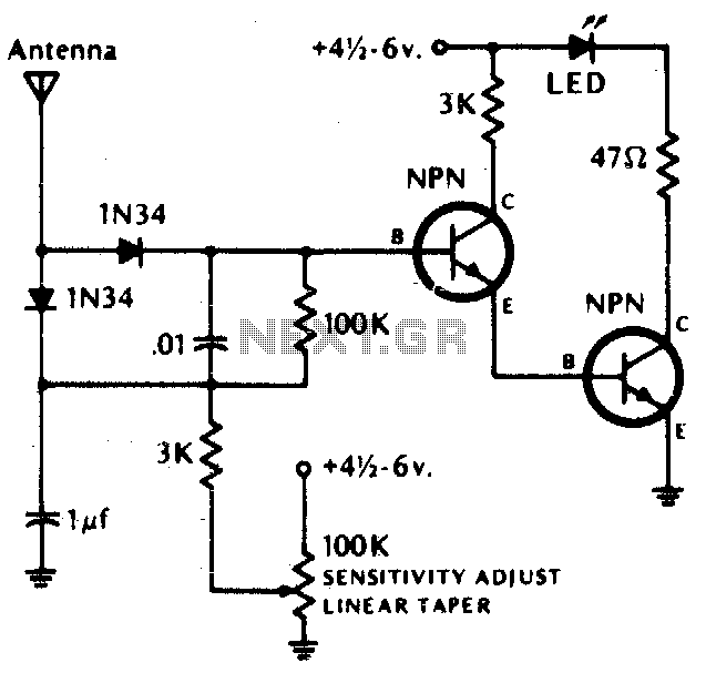
The LED illuminates when the RF field exceeds the pre-set field strength level. Germanium diodes are recommended. Additional information: Transistors (NPN) include 2N2222, 2N3393, 2N3904, or equivalent. The circuit described is a simple RF field strength indicator that utilizes an...
The circuit depicted is designed to protect a system from power supplies that may exceed safe limits. An example of this is small consumer products that utilize external AC adapters, where there is a risk of accidentally connecting the...
The principle discussed pertains to electromagnetic fields in the WFC, highlighting similarities with other concepts, with only minor differences. The electromagnetic fields (EM fields) in wireless frequency communication (WFC) are fundamental in understanding how signals propagate and interact with various...
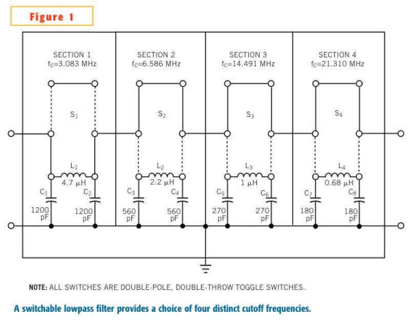
In an adjustable lowpass filter, each filter section uses commonly available components. This example uses filter-section cutoff frequencies for standard inductors and capacitors without the need for any extra components in series or parallel. Fixed inductors are Coilcraft 90...
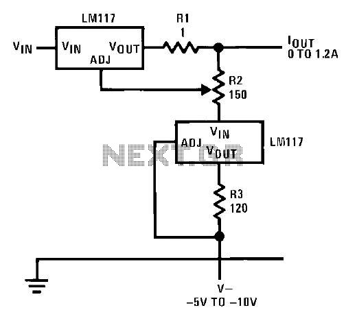
This circuit illustrates an adjustable regulator configuration that incorporates a voltage regulator. In this design, the LM117 regulator is utilized instead of the LM113 diode for reference. Both regulators necessitate a negative supply to function correctly with respect to...
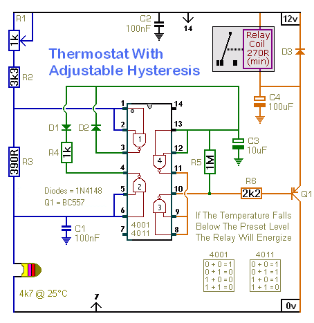
A thermostat doesn't try to maintain a constant temperature. In order to do so, it would have to keep switching on and off every few seconds. Instead, it keeps the temperature within a specific range. When the preset temperature...