
MUSICAL TELEPHONE RINGER
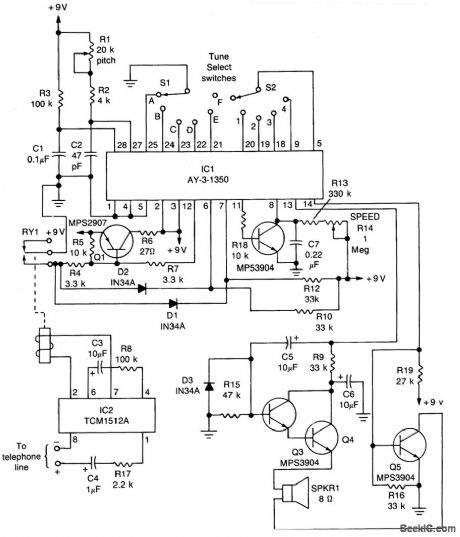
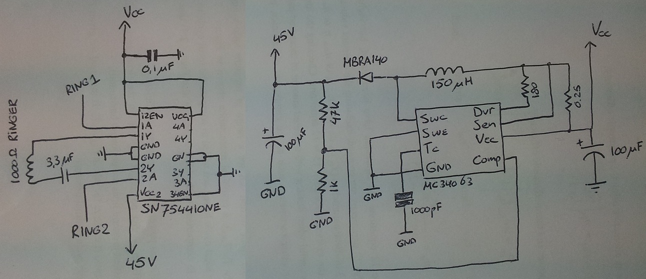
The circuit design centers around two integrated circuits: the AY-3-1350 and the TCM1512, each serving distinct functions essential for melody playback upon incoming phone calls. The AY-3-1350 is a dedicated melody synthesizer capable of generating various tunes through pre-defined sound patterns. It is controlled by an external voltage signal, which in this case is provided by the relay operation initiated by the TCM1512.
The TCM1512 operates by detecting the AC ring signal typically present on telephone lines. This IC is designed to recognize the specific frequency and voltage levels associated with ringing. Upon detection, it converts the AC signal into a usable DC voltage, which activates the relay RY1. The use of an SPST reed relay allows for minimal power consumption and quick switching, making it suitable for low-voltage applications like this circuit.
When the relay closes, it creates a path that pulls down the control pin of the AY-3-1350, enabling the melody generation. The output from IC1 is then amplified by transistor Q2, ensuring that the sound is sufficiently loud when played through the speaker. The circuit is designed to seamlessly transition between active and standby modes, effectively managing power consumption and ensuring that the melody only plays in response to incoming calls.
The operation concludes when the melody finishes or when the phone is lifted off the hook. Lifting the handset interrupts the ring signal, causing the relay to open and the AY-3-1350 to return to its standby state. This design not only provides an auditory alert for incoming calls but does so with efficiency and responsiveness, making it an effective solution for enhancing traditional telephone systems.The heart of the circuit is IC1, General Instrument`s AY-3-1350 melody-synthesizer IC. IC2 is a TCM1512 telephone ring detector IC that is powered by the telephone line. The circuit`s operation begins when IC2 senses a ring pulse on the telephone line. The detector (internally) rectifies the ring signal and then outputs a voltage to relay RY1 (an SPST reed-type relay with 5 volt contacts), causing its contacts to close. That pulls pin 12 (the ON/OFF control) of IC1 low (logic 0 ), causing it to output a signal-the selected tune-to transistor amplifier Q2. The amplified signal is then fed to the speaker. The melody continues to play either until the tune is finished (at which time IC1 returns to the standby mode), or until someone takes the phone off the hook.
Taking the phone off the hook dis-continues the ring pulses to IC2, which opens RY1. When the relay contacts open, pin 12 of IC1 goes high, returning the circuit to the standby mode to wait for the next incoming phone call. 🔗 External reference
Related Circuits
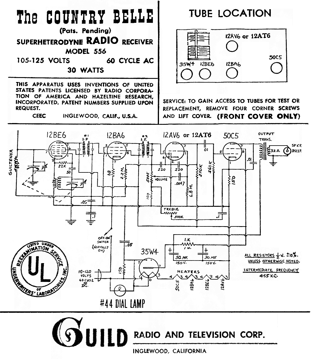
The Guild "Country Belle" is a distinctive novelty radio designed to resemble an old-fashioned wall telephone. Manufactured in large quantities, this model remains relatively common today. It is identified as model 556, and while prices may vary, it is...
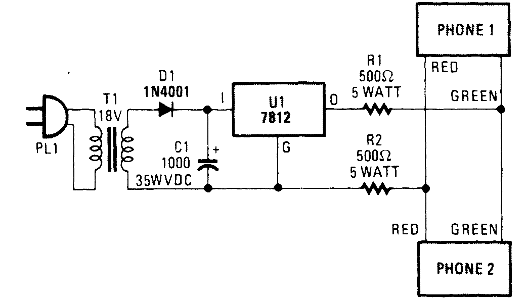
This circuit is designed to generate a loud ringing tone for an electricity bell in older telephones. It serves as a replacement for the original ringer, which may be lost, eliminating the need for a new phone. The circuit...
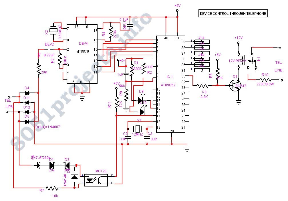
This Project is used to control our household electrical devices from anywhere through the cell phone. The circuit consists of a DTMF tone detector and a powerful 8-bit Microcontroller AT89S52. The microcontroller controls all the system. In this project,...
The process involves adapting an old phone for Bluetooth functionality, specifically testing the ringer circuit constructed using schematics from Sparkfun. When connecting a section of the schematic to a 3.5V source (Vcc), an output voltage of 45V is observed,...
Tro telephones can be utilized as an intercom through the implementation of this circuit. Traditional rotary phones, particularly those that are non-electronic, may be the most effective for this purpose. Additionally, this method can also power handsets alone. The circuit...
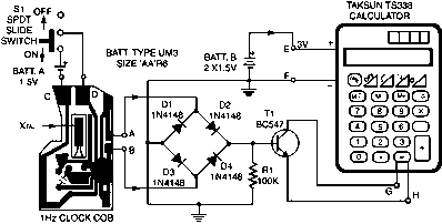
In this circuit, a simple calculator, in conjunction with a COB (chip-on-board) from an analogue quartz clock, is used to make a telephone call meter. The calculator enables conversion of STD/ISD calls to local call equivalents and always displays...