
my gps lcd display project using pic16f84

The project involves the design and implementation of a microcontroller-based system utilizing a PIC (Peripheral Interface Controller) microcontroller. The selection of a PIC microcontroller is pivotal due to its versatility, ease of programming, and wide range of available peripherals. The circuit design typically includes essential components such as power supply circuits, input/output interfaces, and possibly communication modules depending on the intended application.
Power supply design is crucial, often utilizing a voltage regulator to ensure the microcontroller operates within its specified voltage range. Commonly, a 5V or 3.3V regulator is employed, depending on the specific PIC model chosen. Capacitors may be added to the power lines to filter noise and stabilize the voltage.
Input interfaces can include various sensors or user input mechanisms such as buttons, potentiometers, or switches. These components allow the microcontroller to receive data from the environment or user, enabling it to perform tasks based on this input. The design should incorporate appropriate pull-up or pull-down resistors to ensure reliable readings from digital inputs.
Output interfaces may involve LEDs, motors, or displays, allowing the microcontroller to communicate its status or results to the user. The design may also include driver circuits for higher power outputs, such as transistors or relay modules, to control larger loads safely.
If communication with other devices is necessary, protocols such as UART, SPI, or I2C can be implemented, requiring additional components like level shifters or buffers if interfacing with devices operating at different voltage levels.
Overall, this project exemplifies the practical application of embedded systems, combining hardware and software to create a device that fulfills a specific function, showcasing the capabilities of PIC programming and microcontroller technology.This is a project that I started back late 2003 when I just starting to learn PIC programming. I wanted to building something that actually did somthing us.. 🔗 External reference
Related Circuits
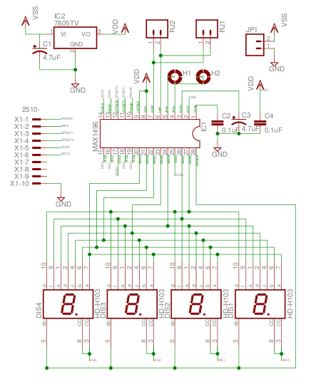
The MAX1496 is an analog-to-digital converter (ADC) that incorporates LED drivers, allowing for the construction of a 3 1/2 digit voltmeter using a minimal number of components. This device features both external and internal voltage reference options, along with...
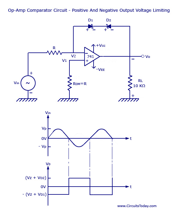
Voltage Limiter Circuit Using Op-amp - Circuit Diagram, Waveform, Positive and Negative Voltage Limiters. The voltage limiter circuit utilizing an operational amplifier (op-amp) serves to restrict the output voltage to predefined levels, effectively preventing it from exceeding or falling below...
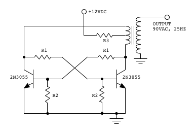
Make two telephones ring on stage. This involves sending a signal down a line to the phones. An old telephone exchange system was initially sought but not found. Several circuit ideas have been discovered, but the goal is to...

This chip from Texas Instruments is easy to integrate into designs and is suitable for the assembly of lighting devices. A consistent quality and expected performance can be easily achieved. The complete circuit consists of a control integrated circuit...
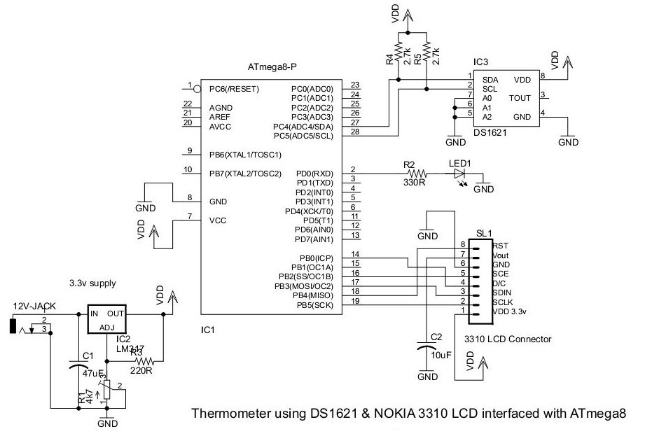
This document presents an application utilizing the Nokia 3310 LCD for designing a thermometer using the DS1621 temperature sensor IC. The DS1621 is an 8-pin sensor manufactured by Maxim. The circuit design involves integrating the DS1621 temperature sensor with a...
This circuit utilizes a 555 timer configured to operate in astable mode. This setup generates a continuous output through Pin 3 in the form of a square wave. When the timer's output transitions to a high state, it triggers...