
N-Channel H-bridge Motor Drive
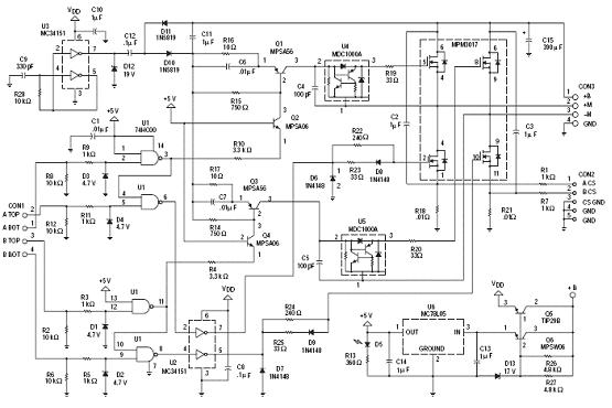
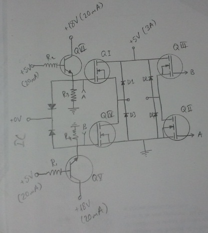
The N-Channel H-bridge motor drive circuit is designed to control the direction and speed of a DC motor using low voltage. The circuit consists of four N-channel MOSFETs arranged in an H-bridge configuration, which allows for bidirectional control of the motor. When the MOSFETs are switched on and off in a specific sequence, the polarity of the voltage applied to the motor can be reversed, enabling forward and reverse operation.
In this configuration, two pairs of N-channel MOSFETs are used: one pair connected to the high side and the other to the low side of the motor. The gates of the MOSFETs are driven by a microcontroller or a dedicated motor driver IC, which provides the necessary control signals. The use of N-channel MOSFETs is advantageous due to their lower on-resistance compared to P-channel MOSFETs, resulting in higher efficiency and reduced heat generation in the circuit.
To ensure safe operation, the circuit may include additional components such as flyback diodes to protect against voltage spikes generated when the motor is turned off. Additionally, current sensing resistors can be incorporated to monitor the motor's current draw, allowing for feedback control and protection features, such as overcurrent shutdown.
The design is suitable for applications where low voltage operation is required, making it ideal for battery-powered devices or small robotics. The simplicity of the H-bridge design allows for easy integration into various projects, providing reliable motor control with minimal complexity.The following circuit shows about N-Channel H-bridge Motor Drive Circuit Diagram. Features: low voltage motor drives, in an N-channel .. 🔗 External reference
Related Circuits
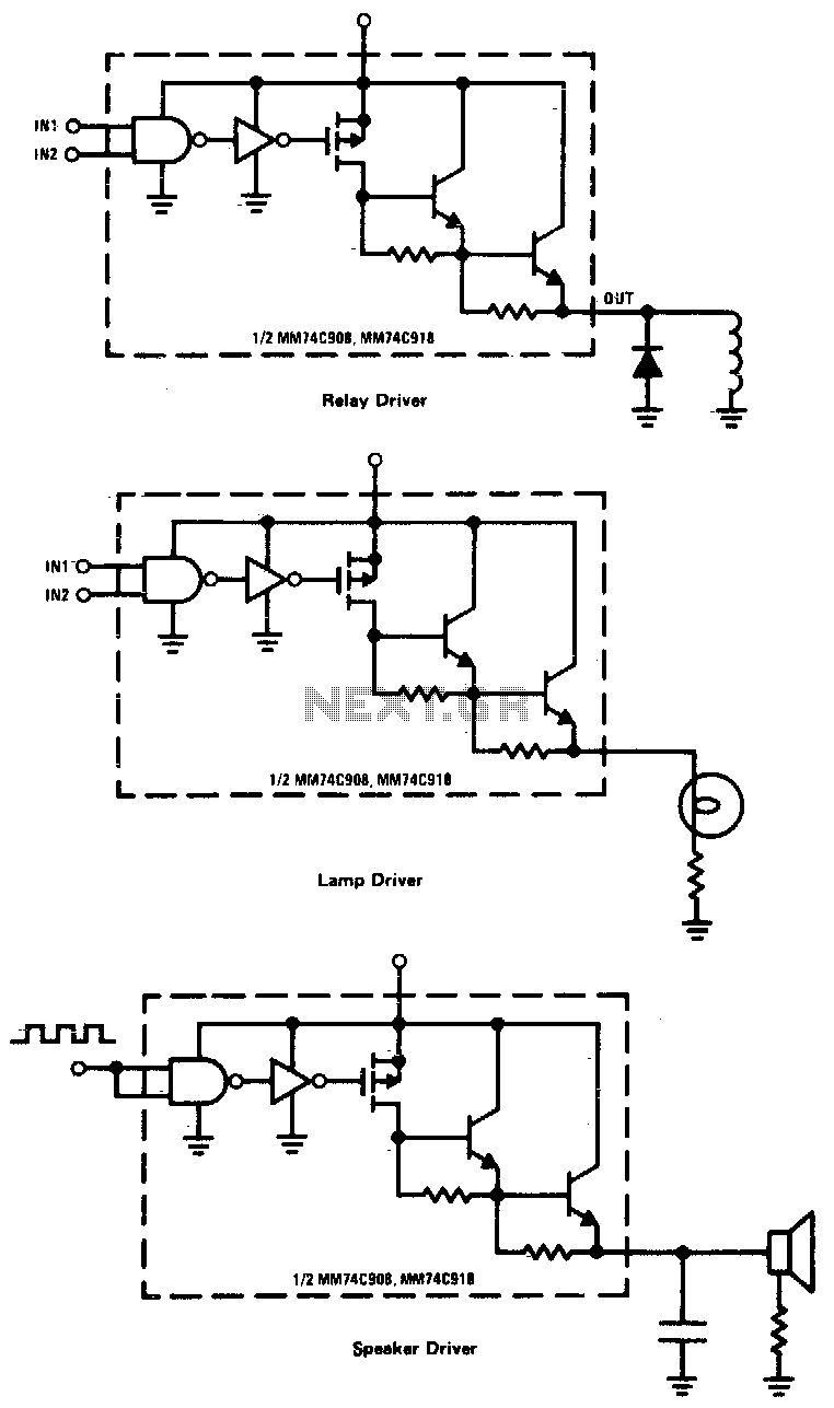
CMOS drivers for relays, lamps, speakers, and similar applications provide extremely low standby power consumption. When operating at Vcc = 15 V, the power dissipation per package is typically 750 nW when the outputs are not drawing current. Consequently,...
Any stepper motor can function as a generator. Unlike other types of generators, a stepper motor generates a significant induced voltage even at low rotational speeds. The specific model used here has a DC resistance ranging from 2 ohms...
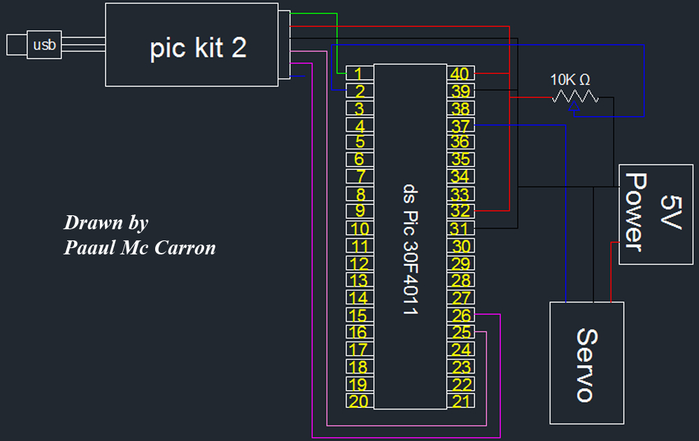
One of the motors utilized in the module is a servo motor. A servo motor is a compact motor that allows for precise positioning at various angles. It is equipped with internal circuitry that automatically maintains the specified angle....
This circuit can control a small DC motor, like the one in a tape recorder. When both the points A & B are "HIGH" Q1 and Q2 are in saturation. Hence the bases of Q3 to Q6 are grounded....
The electronic circuit for steady speed motor applications utilizes an automatic remote control system to regulate the motor power supply, thereby achieving consistent speed control. The circuit diagram illustrates a DC motor connected to the system. Given that the...
An H-bridge is being utilized with IRF740 MOSFETs to convert 315V DC to 230V AC. However, the upper MOSFETs are frequently damaged within a few seconds, and the cause of this issue has not been identified. The described circuit employs...