
N6EX Receiver Mods
The modifications to the Kenwood TK-931 transceiver for 902 MHz repeater operation involve several critical steps to ensure proper functionality and performance. The installation of the audio/buffer interface board is a pivotal modification, as it facilitates the necessary connections for receive audio and signal presence. The location chosen for the interface board is strategic, as it is close to the microprocessor, minimizing the length of the connections and thereby reducing potential interference.
The selection of the audio pick-off points is essential for maintaining audio quality. The unfiltered discriminator audio provides a broader frequency response, which can be advantageous for applications where audio fidelity is paramount. The choice to use this point instead of the filtered version reflects a preference for a flatter response curve, which is particularly useful in digital communication systems where signal integrity is crucial.
The integration of the Audio/COR interface board into the system not only enhances the audio output level but also improves noise immunity. This is particularly important in environments with high electromagnetic interference, where maintaining a clear signal is essential for reliable communication. The use of a trimpot for fine-tuning the output level allows for precise adjustments, ensuring compatibility with various controllers.
The documentation emphasizes the importance of post-modification check-out and alignment, which is critical for ensuring that the transceiver operates within specified parameters after the hardware changes. This step is vital for maintaining the performance and reliability of the transceiver in its new operational context.
Overall, these modifications represent a thorough approach to adapting the Kenwood TK-931 transceiver for enhanced performance in the 902 MHz band, ensuring that users can achieve optimal communication results.This page identifies all the hardware modifications necessary to adapt a Kenwood TK-931 transceiver for 902 MHz repeater receive operation. Not shown here is the effort required to program the radio for the desired operating frequency. This is accomplished using the Kenwood KPG-5D programming software and KPG-4 programming cable, or equivalent.
It also assumes that the receiver portion of the radio was properly operating in its original frequency range prior to modification. Check-out and alignment of the receiver after modification is recommended. The overall receiver modification photo shows the audio/buffer interface board installed in the front, right section of the top cavity of the receiver.
This area is located near the microprocessor of the radio. The board is drilled on the two front corners to coincide with two unused holes in the radio frame. Not only is this area of the radio available for convenient mounting of the interface board, but it also provides the necessary interface points for receive audio and signal present. For the receive audio signal, an unsquelched line is preferred. The audio switching (squelch) of the TK-931 is done prior to the de-emphasis circuitry, therefore any pick-off point will have flat (relatively) audio.
Two easily accessible pick-off points are available in the vicinity of the microprocessor. One point is an unfiltered buffered version of discriminator audio. There is another point that has a sharp filter to remove the PL and DPL signals below 300 Hz. The plot below shows the frequency response of the two points. While some applications may prefer having the low PL frequencies filtered-out prior to injection into the controller and transmitter, I chose to use the unfiltered point. The unfiltered discriminator point offers a much flatter response as compared with the filtered point.
This point is a via located near pin 32 of the microprocessor (IC4). The soldermask can be removed and a small wire can be soldered between this point and the audio input of the Audio/COR interface board. The signal present line is also directly available on top of the receiver circuit board in the vicinity of the microprocessor.
This point is at the intersection of D101 and R118. A small wire can be attached between this point and the COR input of the Audio/COR interface board. This photo shows the interface points for the Audio/COR board. The small via near the corner of the microprocessor IC (IC4) is the discriminator audio pick-off point. The COR input to the buffer board can be wired to the interface between R118 and D101 of the receiver board.
The photo also shows the alternative audio pick-off point. This point is located on the right side of C121. It is a filtered version of discriminator audio that has frequencies below 300 Hz removed. DC input to the Audio/Interface board can be taken from the CN1 connector (connects front panel to main circuit board). Switched 13. 8 VDC is on pin 2 (SB) and return is on pin 3 (GN). Once the Audio/COR board is installed and connected to the receiver interface points, the board can be checked and adjusted.
One of the reasons the buffer board is used is to provide a high level, low impedance audio source to the controller, thereby greatly improving noise immunity. With this particular controller (Arcom RC210), a level of 2 volts peak-to-peak at rated deviation level was found to work well.
A signal generator is used to produce a strong RF signal (-70 dBm) to the receiver. The deviation on the generator is set to maximum rated deviation (in this case +/- 2. 5 kHz) at a modulation rate of 1 kHz. The trimpot on the Audio/COR board is adjusted until 2 volts peak-to-peak is observed. Also verify that the COR output of the board goes from high to low when signal is applied to the receiver (assumes squelch is set to open and close normally). To interface the TK-931 receiver to the controller, the accessory conn 🔗 External reference
Related Circuits
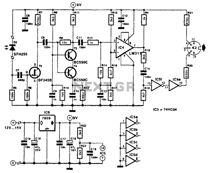
The receiver photodiode SFH250 is utilized to convert optical data pulses at a rate of 32.5 Kbps into electrical signals. The buffer T2 transmits these signals to a cascade amplifier consisting of transistors T3 and T4, followed by an...
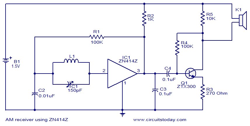
This circuit diagram represents a simple single-chip AM radio, designed around the ZN414Z integrated circuit (IC), which is a ten-transistor tuned radio frequency receiver. The IC features three leads and is housed in a TO92 package. It incorporates all...
Here are the schematics for infrared remotes. This remote transmits a tone using an infrared LED. This tone is decoded by the receiver. Since the receiver only switches when it "hears" the tone, there are no accidental activations. The schematic...
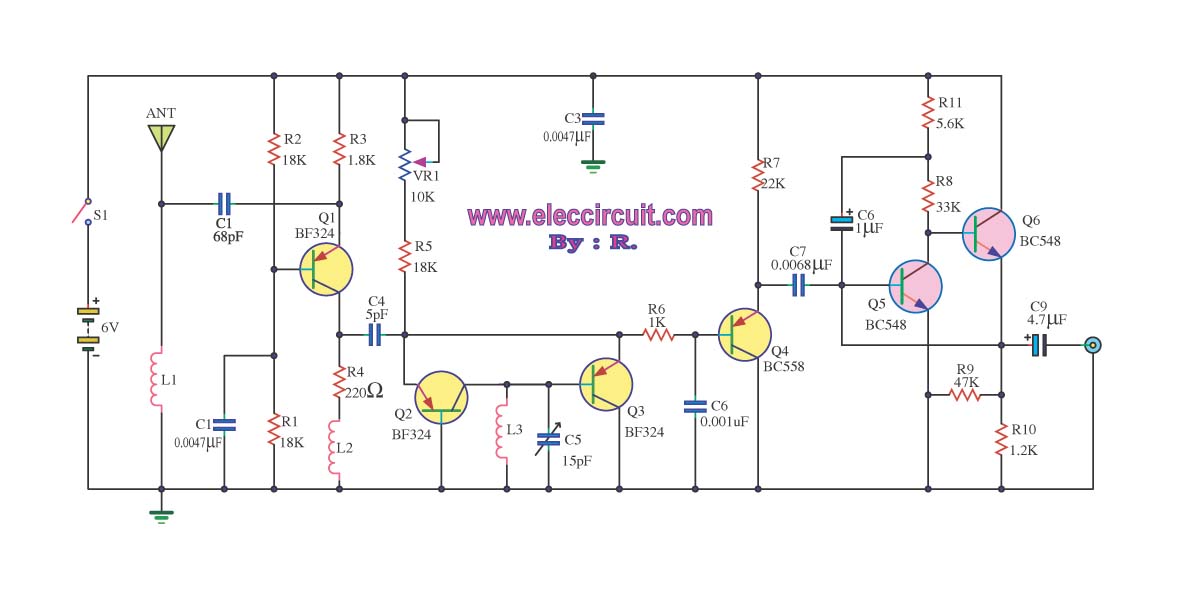
This circuit is an FM radio receiver that is very small in size and operates effectively, although its sensitivity is limited. The principle of this circuit is based on the use of a generator. The FM radio receiver circuit typically consists...
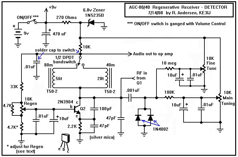
Here is a dual-band regenerative receiver that originated from encouraging communications with Jerry (K9UT) and another individual named Harvey, who constructed the original AGC-80 and its experimental successor, the AGC-80/30. Jerry has expressed his satisfaction with both receivers, noting...
A low-cost continuous wave (CW) superheterodyne receiver operates with a 4.00 MHz intermediate frequency. While there is no automatic gain control (AGC) or RF gain control, the receiver demonstrates good large signal handling capabilities. The design incorporates six bipolar...