
Small FM radio receiver

The FM radio receiver circuit typically consists of several key components, including an antenna, RF amplifier, mixer, local oscillator, demodulator, and audio amplifier. The antenna captures radio frequency signals, which are then amplified by the RF amplifier to improve signal strength. The mixer combines the amplified RF signal with a signal from the local oscillator to produce an intermediate frequency (IF) signal. This IF signal is then demodulated to extract the audio information, which is subsequently amplified by the audio amplifier for output to speakers or headphones.
In a compact design, the circuit may utilize integrated circuits (ICs) to minimize size and enhance performance. The generator mentioned in the description likely refers to the local oscillator, which is crucial for tuning the receiver to specific FM frequencies. The circuit may incorporate variable capacitors or inductors to allow for tuning across the FM band.
Despite its small size, the sensitivity of the receiver can be affected by various factors, including the quality of components, circuit layout, and the design of the antenna. Proper shielding and grounding techniques can help mitigate interference and improve overall performance. Additionally, the use of a better-quality RF amplifier can enhance sensitivity, allowing the receiver to pick up weaker signals more effectively.
Overall, this FM radio receiver circuit is a practical solution for compact radio applications, providing a balance between size and functionality, albeit with some limitations in sensitivity.This circuit is FM radio receiver that very small size and works well, although the sensitivity is poor. The principle of this circuit is to use the generator.. 🔗 External reference
Related Circuits
The second half controls the steering. The mechanical design is a 3 wheeled caddy with the single wheel actually a closely spaced pair of wheels which are driven by the main drive motor to provide motive power (this is...
This circuit diagram represents a radio-controlled system, commonly utilized in toy car applications for children. The circuit comprises two main components: the transmitter and the receiver circuits. The transmitter circuit generates radio signals through an oscillator circuit built with...
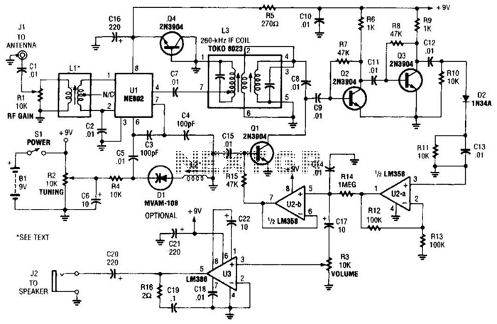
The integrated circuit Ul (an NE602 double-balanced mixer) functions as both an oscillator and a frequency mixer. Signals from the antenna input (at Jl) are transmitted through a DC-blocking capacitor C1 to the RF gain control, Rl, and subsequently...
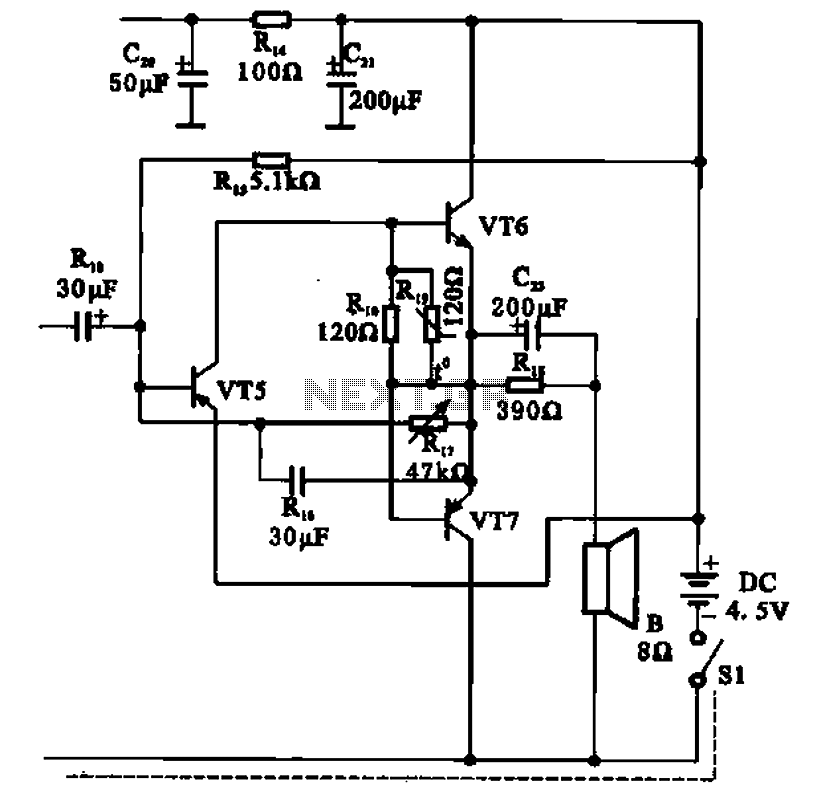
The transistor radio features a common output transformerless (OTL) power amplifier circuit. The VT5 component serves as the bias resistor for the driver stage. VT6 and VT7 form a complementary symmetry configuration, with VT6 being a germanium NPN transistor...
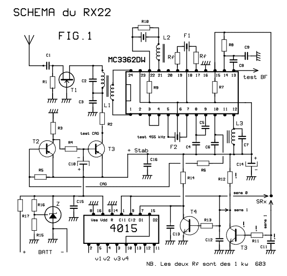
This receiver weighs about 6 g, used in 41 and 72 MHz, met a great success with readers of the magazine. The RX22 is the subject of these lines is improved RX20. Adding a preamp-HF improving sensitivity. Establishment of...
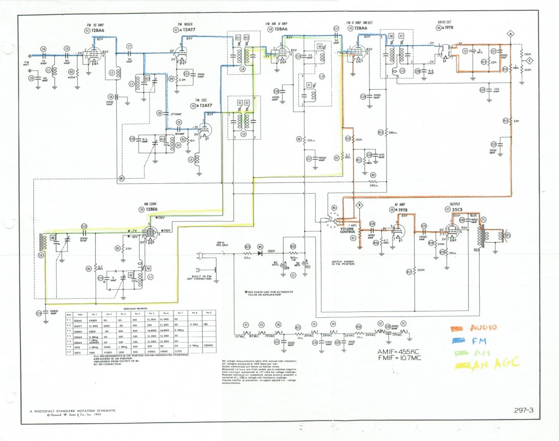
This document outlines the restoration of an antique AM/FM Granco 720 radio. It explores the design of the AM and FM receivers, detailing the alignment of these receivers, discussing repairs, and evaluating the radio's performance. The restoration of antique...