
Infared Remote Control Transmitter-Receiver
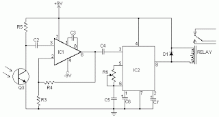
The schematic for the infrared remote control system consists of two main components: the transmitter and the receiver. The transmitter section includes an infrared LED, which is responsible for emitting modulated infrared light. This modulation corresponds to a specific tone or signal pattern, typically generated by a microcontroller or a simple oscillator circuit. The infrared LED is connected to a current-limiting resistor to ensure it operates within its specified current range, preventing damage from excessive current.
The modulation frequency is crucial for the operation of the system, as it defines the tone that the receiver will recognize. Common modulation frequencies for infrared remote controls are in the range of 30 kHz to 40 kHz, which helps to minimize interference from ambient light sources.
On the receiver side, a photodiode or phototransistor is utilized to detect the incoming infrared signal. This component is sensitive to the modulated light emitted by the transmitter. The output of the photodiode is typically fed into a bandpass filter that isolates the modulation frequency, allowing only the desired tone to pass through. This filtering process is essential for ensuring that the receiver only activates in response to the specific signal from the transmitter, thereby preventing accidental activations due to stray infrared signals.
The filtered signal is then processed by a decoder circuit, which is often implemented using a microcontroller or a dedicated IC designed for infrared signal decoding. The decoder interprets the modulated signal and generates a corresponding output, which can control various devices, such as TVs, air conditioners, or other consumer electronics.
Overall, the infrared remote control system is an efficient and reliable method for wireless communication, characterized by its simplicity and immunity to accidental activations, due to the specific tone detection mechanism employed in the receiver.Here`s schematics for infared remotes. This remote transmits a tone using an infared LED. This tone is decoded by the receiver. Since the receiver only switches when it "hears" the tone, there are no accidental activations. 🔗 External reference
Related Circuits
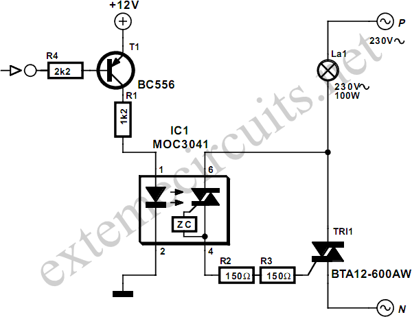
When switching a mains voltage, a relay serves as a straightforward solution for applications involving long switching times and high currents. However, for lower currents and applications requiring rapid switching, such as sound-to-light systems, a relay may not be...
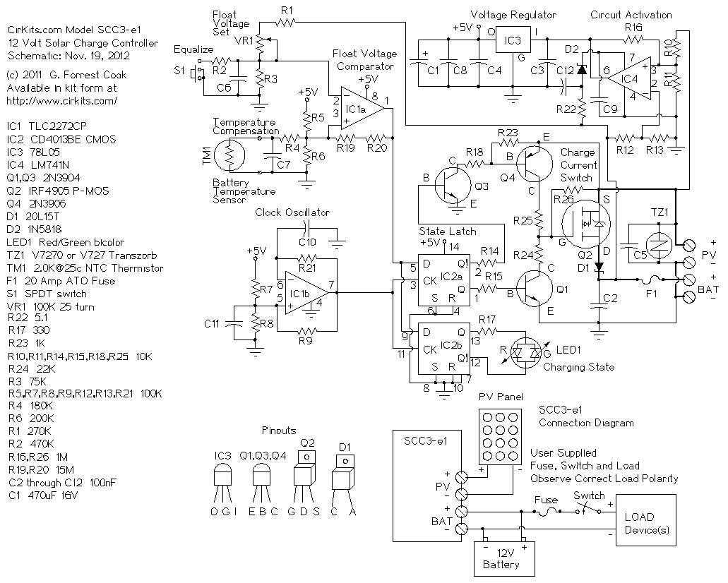
The SCC3 is a solar charge controller. Its function is to regulate the power flowing from a photovoltaic panel into a rechargeable battery. It features easy setup with one potentiometer for the float voltage adjustment, an equalize function for...
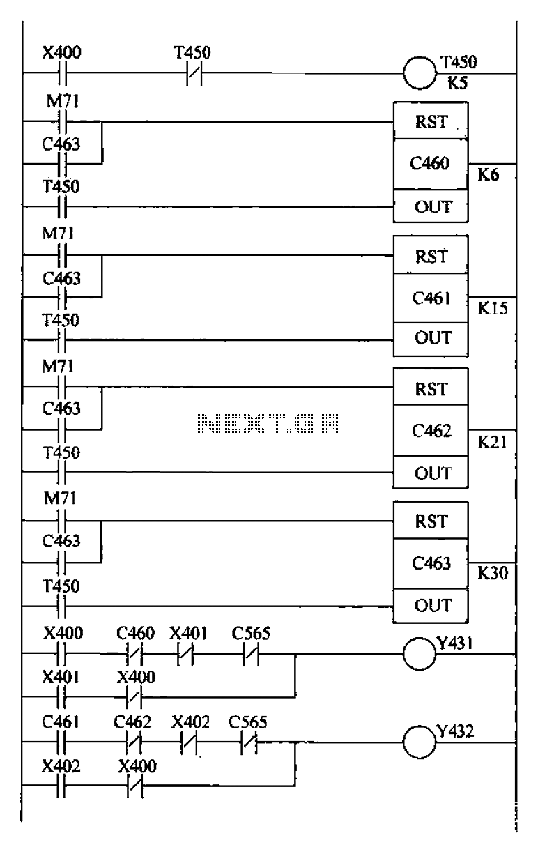
Bridge crane control PLC ladder design includes a detection retract mechanism for ladder hiding, programmed for both manual and automatic operation. The system operates as follows: 1) Upon PLC boot-up, an initialization pulse is generated by internal relay M71,...
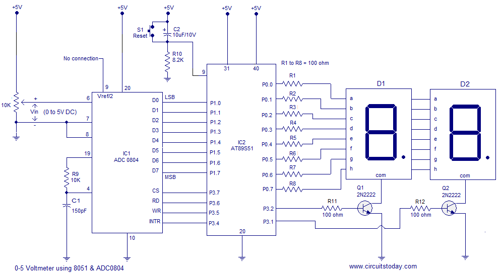
A simple 0-5 digital voltmeter utilizing the 8051 (AT89S51 microcontroller) is presented, accompanied by a circuit diagram and assembly language (ASM) code. This digital voltmeter is designed for straightforward voltage measurement. The circuit employs an AT89S51 microcontroller, which serves as...
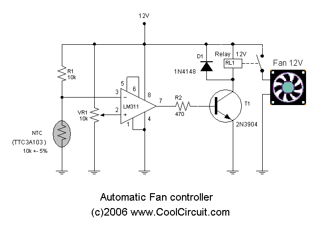
Automatic fan control circuit. This circuit turns a 12V DC fan or CPU fan on or off based on temperature readings. The temperature can be adjusted using VR1. The automatic fan control circuit operates by monitoring the temperature of...
The 3D printer necessitates independent control for three separate axes. Each controlled axis must be equipped with a high-precision electronic driver. The mechanical components of each axis utilize a precise bipolar stepper motor connected to a drive shaft via...
Warning: include(partials/cookie-banner.php): Failed to open stream: Permission denied in /var/www/html/nextgr/view-circuit.php on line 713
Warning: include(): Failed opening 'partials/cookie-banner.php' for inclusion (include_path='.:/usr/share/php') in /var/www/html/nextgr/view-circuit.php on line 713