
NE612AN NE612 mixer / oscylator RF
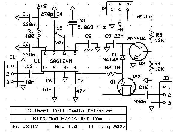
A balanced broadband transformer is constructed by winding a 10-turn:2-turn binocular transformer using 34 AWG wire. The 10 turns are connected across pins 4 and 5 of U1, while the 2 turns are connected to pin 2 of J3 and ground. This configuration is crucial for achieving the desired performance characteristics in the transceiver design, enabling efficient signal processing and transmission for PSK31 communications. The overall system integrates hardware and software components to provide a robust platform for amateur radio enthusiasts to engage in PSK31 digital communication effectively.Combine an inexpensive transceiver, some free software and you`re on PSK31 at a rock-bottom price! Add to that the fun and pride of building the transceiver and you`ve got a n irresistible package! I is a relatively new I digital mode, created Iby Peter Martinez, | G3PLX, and covered in detail in QEX. 1 Because of its narrow bandwidth requirements and the Viterbi decoding built into the mode by Peter, PSK31 is ideally suited to Amateur Radio digital communications using low power. However, the narrow bandwidth of the PSK31 signal ”31. 25 Hz ”makes tuning PSK31 signals somewhat more difficult than tuning SSB and CW signals, because accurate tuning to within only a few hertz is necessary for proper decoding.
This requirement has resulted in several attempts to make tuning easier, such as the PSK31 tuning aid described by Don Urbytes, W8GLV, 2 and the phase scope and waterfall display Peter included in his popular introductory software for PSK31. It was during an e-mail exchange with Peter that I hit on the idea of eliminating the need for tuning altogether!
The concept of the Panoramic Transceiving System for PSK31 was born. As Steve Ford, WB8IMY, put it so well in his article, "PSK31 ”Has RTTY`s Replacement Arrived ", 3 PSK31 signals don`t deedle-deedle like RTTY signals, or chirp like the TOR modes, they warble, sounding like high-pitched, warbling carriers as you tune across them. If several PSK31 stations are operating close together, they sound like a bunch of caterwauling alley cats!
It is virtually impossible to separate the individual stations by ear, as the human hearing cannot distinguish between different tones very close together in pitch, so some other technique must be used to separate stations and the best way to do it is visually*. PSK31 stations are received just like CW or SSB stations, by beating the incoming carrier with another carrier produced by the receiver, creating a beat note, which, in the case of CW, is an on/off tone.
For SSB, it`s a whole series of tones that represent the human voice. Just as it is possible to hear many CW stations at one time as a collection of on/off tones of different pitch, it is possible for many PSK31 stations to also be heard at one time as a collection of warbles. Each station on a slightly different frequency produces a slightly different warbling tone, just as each CW station produces a different keyed tone.
By scanning the audio spectrum containing these warbling tones and displaying the tones graphically as on a spectrum analyzer, each PSK31 station can be seen apart from the others. This task is accomplished by the software part of the system; a program called DigiPan, for digital panoramic tuning.
DigiPan has been released for general use, and is reviewed in detail by Steve in his PSK31 update article. 4 Figure 1 ”A sample of DigiPan`s PSK31 signal display. At the bottom half of the screen, the bar with the diamond-shaped cursor in it (the large bar at the left) is a strong PSK31 station.
(Incoming signals scroll from top to bottom; the newest signals are at the top of the display. ) The ongoing chatter ”complete with typos ”is readable in the top half of the screen above the waterfall display. DigiPan employs digital signal processing (DSP) techniques to decode the PSK31 warbles and present them as characters on a computer display.
A portion of a typical DigiPan spectrum window is shown in Figure 1. The bright yellow bars represent the signals within the passband. The left-most signal with the diamond-shaped cursor in it is a strong PSK31 station to which the receiver is tuned. Time is displayed on the Y axis, progressing from top (most recent) to bottom (past). To tune in and receive any of these stations, all you have to do is use the computer`s mouse to point to the station`s signal and click!
The diamond-shaped cursor jumps immediately to the center of the station signal and the chosen station`s transmitted information appears on screen in a receive window. Other sections of the DigiPan screen are devoted to buttons to control the functions of DigiPan, the receive window and a window for typing outgoing text, you can download a copy of Digifan free on the web at digipan/.
For DigiPan to provide a panoramic display with point-and-click tuning of stations, it is necessary for the transceiver to provide panoramic reception and transmission, which means the transceiver must be a special wideband design, capable of receiving many PSK31 stations at one time. Therefore, the second important element of the Panoramic Transceiving System is the transceiver itself.
There are characteristics of PSK31 communication that dictate (and to some extent simplify) the transceiver design. The narrow width of a PSK31 signal demands a very low-drift design, typically less than 5 Hz over the course of a QSO.
However, the narrow signal width also means lots of stations fit into a very narrow slice of spectrum! The fortunate result is that it is possible to make a simple, low-drift, crystal-controlled receiver and transmitter and let the software perform the tasks of displaying the signals on the band and tuning them in.
The TR switching requirements prove to be quite simple. Unlike CW, there is no need for perfectly shaped keying or fast break-in, and the transmit/receive function need be no more complicated than throwing a switch. To ensure the most reliable TR switching, we elected to use a standard RS-232 signal (RTS or DTR) available at the computer`s serial port to control the TR changeover.
To properly transmit and receive a PSK31 signal, it is necessary that the transmitter and receiver be operated linearly. Although it is still possible to overdrive the transmitter or otherwise operate in a nonlinear range and have the signal decoded successfully at the receiving end, you won`t win any friends on nearby frequencies!
The spectrum of an overdriven transmitter signal extends well beyond the normal narrowband signature. With the panoramic display, your signal spectrum is displayed for all to see, and you`re sure to get meaningful feedback from the stations you`re in QSO with or who are on nearby frequencies!
Dave: When Howard contacted me regarding the use of an existing linear SSB design for a PSK31 transceiver, 51 was naturally curious as to the modifications necessary to yield reliable operation. Those amounted to extensive changes to improve the LO stability, as discussed later, and a new TR switching mechanism.
Howard had developed a small outrigger board that contained the necessary PSK31 circuit functions, but the additional modifications to the existing board didn`t lend themselves readily to ease of reproduction. To eliminate the need for the hand wiring and modifying an existing SSB transceiver, I agreed to incorporate the changes into a clean new layout.
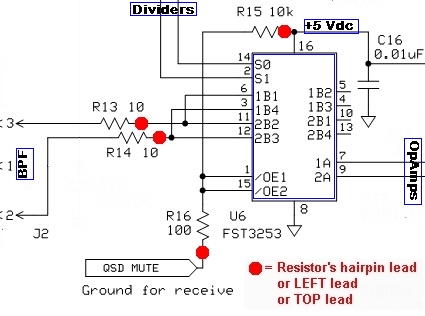
The result of this collaboration is shown in the schematic of Figure 2. The following discussion highlights the changes with respect to that earlier design. 2. Balanced broadband; wind a 10turn:2turn binocular transformer using the 34 GA wire and connect the 10 turns across pins 4 and 5 of U1. Connect the 2 turns to pin2 of J3 and ground. 🔗 External reference
Related Circuits

A balanced diode mixer circuit is presented, utilizing two diodes, specifically the 2AP9 model. The circuit operates with a high voltage, causing the diodes to function in an off state, which is also referred to as a diode switch...
The objective of this project was to design a small portable mixer powered by a 9V PP3 battery while maintaining performance quality. The mixer consists of three main modules that can be varied in number and can be adapted...
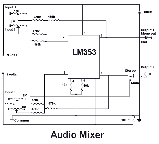
With this circuit you can mix four separate audio inputs. Each input will accept high or low impedance microphones, phonograph, tape or aux signals. You can adjust the gain of each input by adjusting each respective pot. With the...
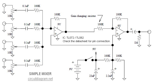
This is a simple mixer featuring four inputs and two operational amplifiers (op-amps). It is designed for mixing microphones or effects outputs. The overall gain from input to output is unity when the potentiometer associated with the input is...

This technical note focuses on determining the system specifications of a CDMA receiver to establish practical specifications for a low noise amplifier and down converter. The design of a CDMA (Code Division Multiple Access) receiver necessitates a comprehensive understanding of...
In the "DSP" tab's "Local Oscillator" section, click on the button labeled "Single Band" and enter the desired center frequency (7046000). This configures Rocky's center frequency to 7.046 MHz. Set up the transceiver or another signal source to transmit...