
Negative Voltage Load Swtich
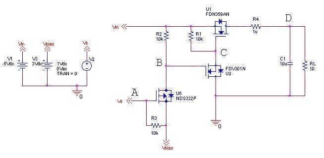
The good thing about this design is that I can make use of the system I/O voltage to control the on/off and this is the whole idea. However, there are many types of load switches that turn off negative voltages. Here is the suggestion,
A circuit that controls negative voltage loads can be implemented using a load switch designed specifically for this purpose. The primary function of this circuit is to manage the power delivery to loads that require a negative supply voltage, such as bias voltages for LCD panels, RF amplifiers, and audio amplifiers.
In this design, a load switch IC capable of handling negative voltages is utilized. The load switch will typically have an input pin connected to the system's I/O voltage, which acts as the control signal. When the I/O voltage is high, the load switch allows the negative voltage to pass through to the load, thus powering it on. Conversely, when the I/O voltage is low, the load switch disconnects the negative voltage from the load, effectively turning it off.
The load switch IC should be selected based on several parameters, including the maximum current rating, the voltage drop across the switch (on-resistance), and the maximum negative voltage it can handle. Additionally, it is important to consider the switching speed, which can affect the performance of sensitive applications such as RF amplifiers.
To ensure stable operation, bypass capacitors should be placed close to the load switch, particularly on the input and output sides. This helps to filter out any noise and provides a stable voltage supply during switching events.
For applications requiring precise control, a microcontroller can be employed to manage the I/O voltage signal, allowing for programmable control of the load switch. This adds flexibility to the design, enabling the system to turn off the negative voltage load under specific conditions, such as when the device enters a low-power state or when certain operational thresholds are met.
In summary, the proposed circuit efficiently manages negative voltage loads using a dedicated load switch controlled by the system's I/O voltage, providing a reliable solution for applications such as LCD biasing, RF amplification, and audio signal processing.The idea is simply to turn off the negative voltage load. Some examples:- - Bias votlages for LCD panels - RF Amplifiers - Audio Amplifiers The good thing about this design is that i can make use of the system i/o voltage to control the on/off and this is the whole idea. However, there are many many type of load switches that turn of negative voltages. Here is the suggestion, 🔗 External reference
Related Circuits

In this circuit, IC1 (CD4009) is utilized as a square-wave oscillator operating at approximately 25 kHz. Capacitor C1 and resistor R1 determine this frequency. Capacitors C2, diode D1, diode D2, and capacitor C3 create a peak-to-peak rectifier, which produces...
A high voltage power supply is a valuable source that can be effectively used in various applications, such as biasing gas-discharge tubes and radiation detectors. This type of power supply can also serve as a protective measure, such as...
The most effective method for measuring current in a circuit is to insert a sense resistor into the current path. A higher resistance results in a more accurate measurement; however, it can also impact the circuit's operation. Utilizing an...
There is one significant low-impedance node in the entire circuit, referred to as 0V, located at the frame and the intersection in the middle. The upper voltage source is connected to this midpoint through a 1kΩ resistor, indicating that...
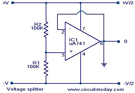
Voltage splitter using op-amp uA741 IC, circuit diagram, working, description. The voltage splitter circuit utilizing the uA741 operational amplifier (op-amp) is designed to provide a stable output voltage that is a fraction of the input voltage. The uA741 is a...
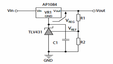
The following schematic illustrates the method for increasing the output voltage of a fixed linear regulator circuit using 3-terminal shunt regulators or references. These 3-terminal shunt regulators enhance the functionality of medium accuracy linear regulators, transforming them into precision...