
simple but reliable car battery tester

The circuit design leverages the LM3914, which is a dot/bar display driver IC designed to drive LED displays in either a bar graph or dot mode. The high-impedance voltage divider ensures minimal loading on the battery, thus providing accurate voltage readings. The design involves connecting the car battery to the voltage divider, which consists of two resistors arranged to scale down the input voltage appropriately. The output of this voltage divider is then fed into the LM3914, which interprets the voltage level and drives the corresponding number of LEDs based on the input voltage.
The internal voltage reference of the LM3914 is crucial for ensuring that the output is stable and accurate. By providing a fixed 1.25V reference, the circuit can effectively translate the scaled-down voltage into a visual representation on the LED display. The inclusion of the offset trimmer allows for calibration of the circuit, accommodating variations in battery voltage that may occur due to load or battery health.
The smoothing capacitor serves a critical role in maintaining measurement accuracy by filtering out any transient noise from the ignition system, which is particularly relevant when the engine is running. This ensures that the voltage readings reflect the true battery voltage without interference from electrical noise generated by the engine's operation.
In summary, this circuit provides a reliable means of monitoring car battery voltage with the flexibility of adjusting the measurement range and display mode, making it a valuable tool for automotive diagnostics.This circuit uses the popular and easy to find LM3914 IC. This IC is very simple to drive, needs no voltage regulators (it has a built in voltage regulator) and can be powered from almost every source. When the test button is pressed, the Car battery voltage is feed into a high impedance voltage divider.
His purpose is to divide 12V to 1, 25V (or l ower values to lower values). This solution is better than letting the internal voltage regulator set the 12V sample voltage to be feed into the internal voltage divider simply because it cannot regulate 12V when the voltage drops lower (linear regulators only step down). Simply wiring with no adjust, the regulator provides stable 1, 25V which is fed into the precision internal resistor cascade to generate sample voltages for the internal comparators.
Anyway the default setting let you to measure voltages between 8 and 12V but you can measure even from 0V to 12V setting the offset trimmer to 0 (but i think that under 9 volt your car would not start). There is a smoothing capacitor (4700uF 16V) it is used to adsorb EMF noise produced from the ignition coil if you are measuring the battery during the engine working.
Diesel engines would not need it, but I`m not sure. If you like more a point graph rather than a bar graph simply disconnect pin 9 on the IC (MODE) from power. 🔗 External reference
Related Circuits
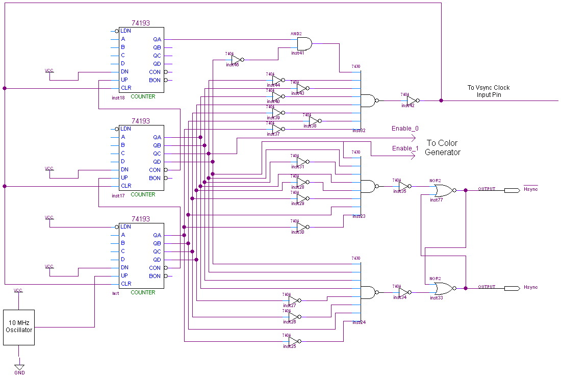
The complete schematic for this project is quite extensive. To view it, please click the image below. Due to its size, the explanation of the connections is divided into three sections: the Hsync Generator, Vsync Generator, and Color Generator....
A novel application of solar cells simplifies the process of positioning a car in a garage, offering an improvement over traditional methods such as using old tires, mirrors, or chalk marks. The six solar cells depicted in Figure 1...
A multi wire cable tester with a separate LED for each wire. Will show open circuits, short circuits, reversals, earth faults, continuity and all with four IC`s. Designed initially for my intercom, but can be used with alarm wiring,...
This circuit can be utilized as a replacement for the single current-limiting resistor typically found in low-cost battery chargers. The alternative presented here is advantageous because it prevents the premature failure of nickel-cadmium (NiCd) batteries, which often occur after...
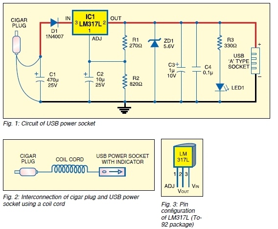
The safe 12V car adapter described here can be used to limit the current from a +12 volt car battery, available from the in-dash cigar lighter power port, to below 2.6A. The 12V car adapter is designed to ensure that...
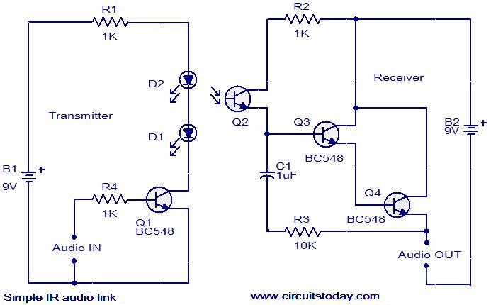
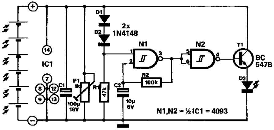
This circuit features a simple infrared (IR) audio link designed to transmit audio signals over a distance of up to 4 meters. The audio signal to be transmitted is applied to the base of transistor Q1 through resistor R4....