
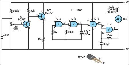
9V NiCd battery charger
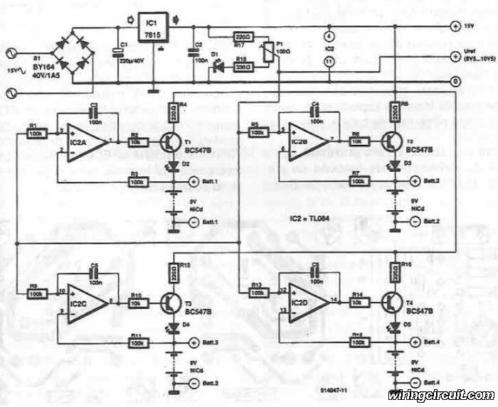
The described circuit operates by utilizing a basic charging topology suitable for NiCd batteries, which are known for their robustness and ability to deliver high discharge rates. The circuit includes a power supply unit that provides the necessary voltage and current to charge the batteries. The four battery slots are connected in parallel, allowing them to be charged simultaneously while ensuring that each battery receives the appropriate voltage.
The potentiometer P1 serves as a variable resistor, enabling the user to adjust the output voltage to match the specific requirements of the NiCd batteries being charged. This feature is critical, as charging voltages must be carefully controlled to prevent overcharging, which can lead to reduced battery life or even damage.
In addition to the charging mechanism, the circuit may incorporate various safety features, such as overcurrent protection, thermal cutoff, and possibly a LED indicator to signal when charging is in progress. These enhancements improve the reliability and safety of the charging process, making it suitable for both personal and professional applications.
Overall, the circuit diagram provides a clear and effective solution for charging multiple NiCd batteries, ensuring that they are charged efficiently and safely.Using this electronic circuit diagram can be designed a very simple charging circuit for NiCd batteries. This electronic charger allows simultaneous charge of four NiCd batteries of 9 V, cursor of P1potentiometer set voltage that will used..
🔗 External reference
Related Circuits
BattMan II is a computer-controlled battery manager designed for typical rechargeable batteries utilized by R/C and electronics hobbyists, as well as various consumer product batteries. BattMan II supports Nickel-Cadmium (NiCd), Nickel-Metal-Hydride (NiMH), Lithium-Ion (Li-Ion), Lithium-Polymer (LiPo), Lithium-Nano-Phosphate (LiNP), and...
A simple method of charging a battery from a higher voltage battery is shown in the circuit below to the left. Only one resistor is needed to set the desired charging current and is calculated by dividing the difference...
A portable phone charger designed for a Siemens mobile phone has been updated to include a printed circuit board (PCB), a USB connector, and enhanced current capabilities. The new charger utilizes a step-up converter based on the TPS61032, which...
This design integrates power-on and low-battery indications, capable of operating with any battery voltage up to 15V. It features a very low current drain of 2mA or less and costs less than $3.50 with new components. When the battery...
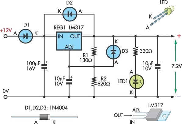
This circuit allows an external 12V SLA battery to power a camcorder that typically uses a built-in 7.2V battery. Obtaining such batteries for older camcorder models can be challenging and costly. The circuit utilizes a standard LM317 adjustable voltage...
It is difficult to envision modern society without batteries. The number of devices in a household powered by batteries is often surprising. Most of these devices utilize penlight batteries, and environmentally conscious users tend to prefer rechargeable batteries. In...