
Netduino Mini

The basic circuit referenced involves utilizing a Netduino Mini, which is a microcontroller platform that combines the capabilities of .NET Micro Framework with the hardware features of a traditional microcontroller. The circuit design typically includes essential components such as resistors, capacitors, and various input/output devices to facilitate interaction with the microcontroller.
In this configuration, the Netduino Mini serves as the central processing unit, executing programmed instructions that control the behavior of connected components. The circuit may include sensors that provide input to the microcontroller, such as temperature sensors, light sensors, or motion detectors. Outputs could involve LEDs, motors, or other actuators that respond based on the input data processed by the Netduino.
Power supply considerations are crucial in this design, ensuring that the Netduino Mini and all connected peripherals operate within their specified voltage and current ratings. Proper grounding and signal integrity must also be maintained to prevent noise and ensure reliable operation.
The schematic layout should clearly indicate the connections between the Netduino Mini and the various components, including pin assignments for digital and analog inputs/outputs. Additionally, the use of breadboards or custom PCBs may be considered to prototype the circuit before finalizing the design for production or deployment.
Overall, the integration of these components into a coherent circuit enables the development of various applications, such as home automation systems, robotics, or interactive installations, leveraging the capabilities of the Netduino Mini platform.I am currently following the two guides here: Original Guide Hackerspace/Coding4fun Thundergod Guide using netduino mini This is the basic circuit. But I would l .. 🔗 External reference
Related Circuits
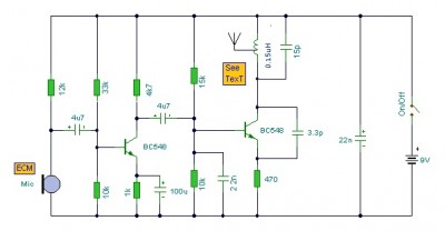
This is a mini FM transmitter circuit that utilizes two transistors. The audio sensitivity is notably high when paired with an ECM type microphone. The transmitter operates using a Hartley oscillator configuration. Typically, the capacitor in the tank circuit...
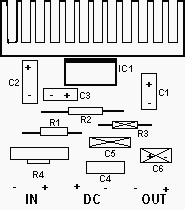
You can use this powerful amplifier in any small audio project. It is very small (6.5 x 4.5 cm). It outputs 10W and uses a 9V battery. More: Components List R1: 6 Ohm R2: 220 Ohm R3: nothing R4:...
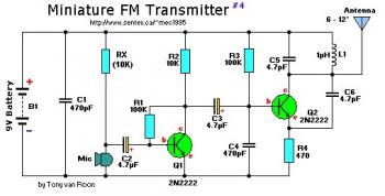
This small FM band transmitter utilizes only two 2N2222 transistors and is capable of transmitting signals up to 1 kilometer away, provided there are no obstacles between the two antennas. The circuit features a microphone preamplifier stage with the...
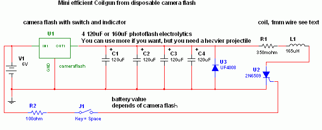
This is a fun and non-dangerous project for individuals interested in launching projectiles using magnetic forces. The mechanism operates by positioning a ferromagnetic projectile at one end of a coil and applying a power pulse. The critical aspect is...
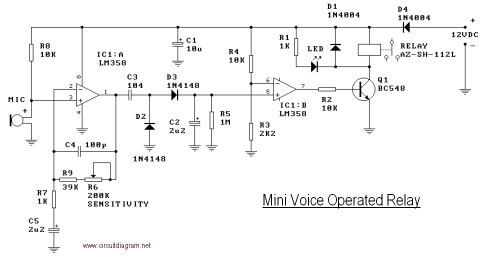
This mini-VOX voice-operated relay is based on a circuit published in Silicon Chip, September 1994, page 31. The off-delay time can be adjusted by varying resistors R3 and R4. Reducing R3 will result in a longer release time. It...
The mine railway connects the national railways and intermediate links of the mining area, serving as an important component of the railway transport network. Statistics indicate that the Chinese mine railway extends over 20,000 kilometers, with numerous road junctions...