
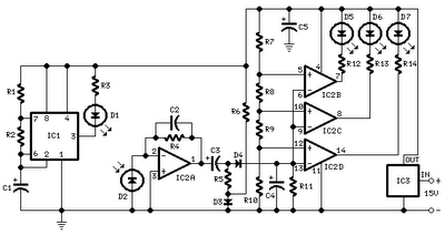
Mini Operated Voice Relay Schematic

This mini-VOX voice-operated relay circuit provides a flexible solution for controlling devices based on voice activation. The core functionality is derived from a design that utilizes a microphone to detect sound levels, which then triggers a relay to operate connected devices. The relay's operation can be finely tuned through the resistors R3 and R4, allowing for precise control over the delay time before the relay disengages.
The adjustment of the release time is critical for applications such as lighting control, where a delay is desired to prevent the light from turning off immediately after the voice command ceases. By changing the capacitor C2 and resistor R5, the time constant can be extended to approximately 30 seconds, providing ample time for the user to leave the room or perform other tasks before the light turns off.
Using a potentiometer or trimpot instead of fixed resistors for R3 and R4 allows for easy on-site adjustments, enhancing the usability of the circuit. This feature is particularly advantageous in prototype or experimental setups where conditions may vary. It is important to note that increasing the capacitance of C2 to 10µF and adjusting R3 to 3.3MΩ will effectively achieve the desired delay without compromising the circuit's integrity.
The circuit layout should be carefully designed to accommodate the additional components required for the adjustable resistors. Sufficient space on the PCB will ensure that the modifications do not interfere with the overall functionality of the circuit. For those interested in building this circuit, kits are available from reputable sources such as kitsrus.com and electronickits.com, providing an accessible entry point for enthusiasts and professionals alike.This mini-VOX voice operated relay is based on a circuit published in Silicon Chip, 9/1994, p31. The off delay time may be adjusted by varying R3 and R4. Reducing R3 will result in a longer release time. You could change the release time constant (C2 & R5) to say 30 seconds and use the VOX as a light switch with this delay time before turn ing off. Increase C2 to say 10uF and R3 to 3M3. To make the easy adjustment, you may use potensiometer or trimpot to varying the value of resistor. You will need additional place on the PCB but it will easier for you to make some adjustment The kit of this circuit available at kitsrus. com anf electronickits. com, you may buy the circuit there. 🔗 External reference
Related Circuits
This circuit was designed to assist in parking a car near a garage wall while reversing. LED D7 lights up when the distance to the wall is approximately 20 cm. When the distance reduces to about 10 cm, both...
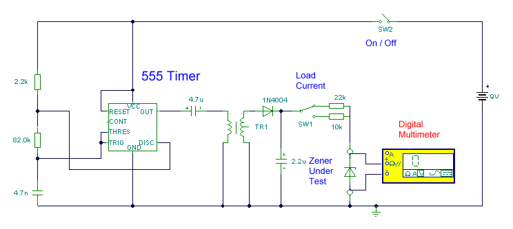
This circuit utilizes a single 555 Timer IC along with a small transformer to generate high voltage for testing zener diodes with voltage ratings up to 50VDC. The 555 timer operates in astable mode, with the output from pin...
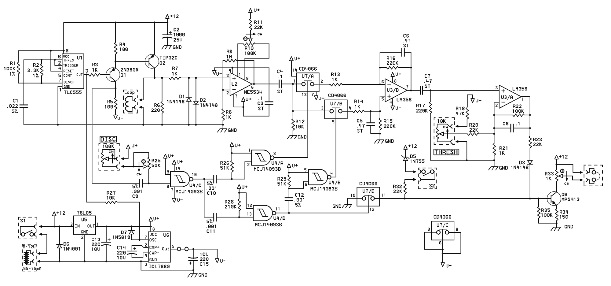
If the TIP32C (Q2) transistor becomes excessively hot, consider replacing it with an IRF9640 MOSFET. It is advisable to experiment with different resistor values for R6 to determine the optimal resistance (a 390-ohm resistor is recommended). A trim potentiometer...
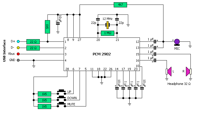
This USB circuit utilizes an integrated circuit (IC) to convert digital voice data into an analog format, making it suitable for headphone use. Additionally, the output can be amplified through a power amplifier, allowing the sound to be played...
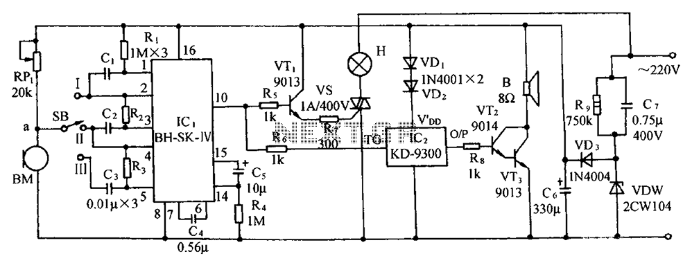
The circuit includes a microphone transducer, voice circuits, an SCR control circuit, a vocal music buck rectifier circuit, and an AC circuit. The BH-SK-IV serves as the core of the device. The described circuit is a complex assembly designed to...
This article discusses the utilization of old PCs as simple controllers. Many obsolete systems, such as the 8088, 8086, 80286, 80386, and 80486, are no longer capable of running modern software, yet they can still function effectively. Often, individuals...