
Stepping motor driver

Stepping motors operate by converting electrical energy into precise mechanical movement, making them ideal for applications requiring accurate positioning. The use of MOSPOWER transistors as motor drivers enhances the efficiency and reliability of the system. These transistors are designed to handle high currents and voltages while avoiding the second breakdown phenomenon, which can compromise performance and longevity.
In this configuration, the absence of snubbing networks simplifies the circuit design. Snubbing networks are typically used to mitigate voltage spikes caused by inductive loads; however, with MOSPOWER transistors, such measures are redundant due to their robust design. The relatively low inductance of the stepping motor further minimizes the risk of inductive spikes, allowing for direct interfacing with the control circuitry.
The connection of the MOSFET gates to the outputs of the CMOS control circuitry facilitates seamless operation. CMOS technology offers low power consumption and high noise immunity, making it suitable for controlling the precise sequencing of the stepping motor. The logic is designed to sequence the motor based on the application's specific needs, ensuring optimal performance and responsiveness.
This design approach not only enhances the reliability of the motor control system but also allows for flexibility in application. By tailoring the logic to the particular requirements, various operational modes can be implemented, such as full-step, half-step, or micro-stepping, providing a range of motion control options. Overall, the integration of MOSPOWER transistors and CMOS control circuitry in stepping motor applications represents a robust solution for modern electronic designs.Stepping motors find wide use in disk drives and machine control. MOSPOWER transistors are ideal motor drivers because of their freedom from second breakdown. Note that snubbing networks are not used because load line shaping is not necessary with MOSPOWER and the inductance of the motor is fairly low so that the inductive spike is small. The MOSFET gates are tied directly to the outputs of the CMOS control circuitry. The logic is arranged to sequence the motor in accordance with the needs of the application.
Related Circuits

This Spark Can Be Very DANGEROUS, So BE CAREFUL. WARNING: FAILURE TO DO SO: WILL CAUSE THE CASE OF THE COIL TO ALSO BE ELECTRIFIED! NOTE You MUST have a LOAD on the High Voltage Output. With NO LOAD,...
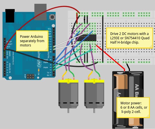
Motor shields functioned effectively; however, they are priced around $50 each, which is more than the cost of the Arduino itself. While this is acceptable for a single unit, it presents a challenge for an Arduino workshop aimed at...

The M-88L70 is a complete DTMF receiver that combines both band-split filter and decoder functions into a single 18-pin DIP or SOIC package. It is manufactured using CMOS process technology, which allows for low power consumption (maximum 18 mW),...
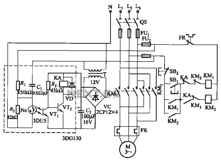
In certain applications, it is crucial to allow a motor to operate in only one specific direction, even when the power supply phase sequence is incorrect. This situation may arise due to external factors, such as incorrect wiring after...
The individual has been engaged in garden railroading for just over a year, utilizing skills from various hobbies. They have designed and built two scratch-built bridges and nearly 100 trestle bents to support a 200-foot main line. Their interests...
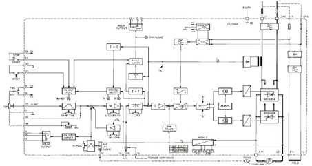
This figure represents the 4Q2 DC Motor Speed Controller Circuit Block Diagram, designed for comprehensive control of conventional shunt-wound and permanent magnet motors with a capacity of up to 75 kW, as specified in the datasheet. This type of...