
Two Speed Contactor DC Motor Controller
The contactor controller described utilizes a straightforward design that leverages mechanical relays to control the power supplied to a motor, making it suitable for applications such as electric scooters. The core components include three 12V relays, which serve as switches to connect or disconnect the motor from the power source. The relays are activated by the two switches, allowing the user to select between different operational modes.
In this configuration, when the relays are arranged to connect the batteries in parallel, the system provides a lower voltage but higher current output, which is ideal for slow-speed operation. Conversely, when the relays switch to connect the batteries in series, the voltage doubles, providing higher speed to the motor. This dual functionality is achieved without the complexity of electronic speed controllers, making the design robust and reliable, as it avoids potential failure points associated with semiconductor components.
The use of two 12V batteries ensures that the system can maintain a balanced discharge rate, extending battery life and efficiency. When the motor is not in use, the batteries are configured in parallel, allowing for easy recharging without requiring complex circuitry. This design choice not only simplifies the overall system but also enhances user safety and maintenance ease.
To implement this circuit, careful consideration must be given to the relay specifications, ensuring they can handle the current and voltage requirements of the motor. Additionally, the switches should be rated appropriately to handle the load and provide a reliable interface for the user. Overall, the contactor controller is an effective solution for controlling motor speed in electric vehicles, emphasizing simplicity and reliability.The simplest of all motor controllers (besides a straight on/off switch) is the contactor controller. Aaron designed this contactor controller for use in his electric scooter project . It is based around three 12V relays, two 12V batteries, two switches and of course a motor. Having no silicon to "fry", it is quite reliable and robust. A contactor controller works by rearranging the two (or more) supply batteries between series and parallel.
This gives the motor a slow speed (batteries in parallel, current adds) and a fast speed (batteries in series, voltage adds). This assures that both batteries are discharged equally. When the circuit is "at rest", the batteries are connected in parallel, which allows easy recharging.
🔗 External reference
Related Circuits
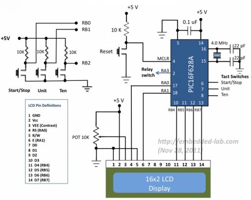
A source code for a simple PIC-based digital timer is provided. The hardware for the project is not available; however, it will be demonstrated using a DIY PIC16F628A breadboard module and I/O board. The complete circuit diagram and firmware...
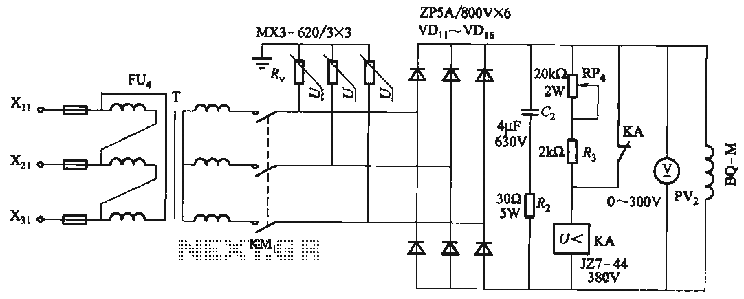
FIG T is the excitation transformer, R is a varistor, and there are rectifier diodes to protect against breakdowns from VDii to VD16; Rz and C2 provide resistive-capacitive protection. The circuit is designed to absorb voltage from the magnetic...
Standard serial interfacing of a microcontroller (TTL) with a PC or any RS232C standard device requires a TTL to RS232 level converter. A MAX232 is used for this purpose. It provides a 2-channel RS232C port and requires external 10µF...
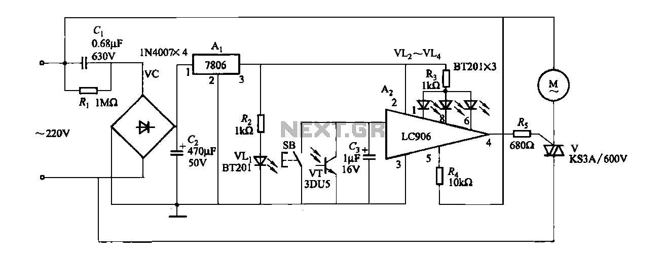
The ceiling fan speed control circuit depicted in Figure 3-6 utilizes a capacitor step-down method and a three-terminal fixed 7806 voltage regulator. It achieves fan speed control through the integrated circuit A2, which regulates the conduction angle of the...
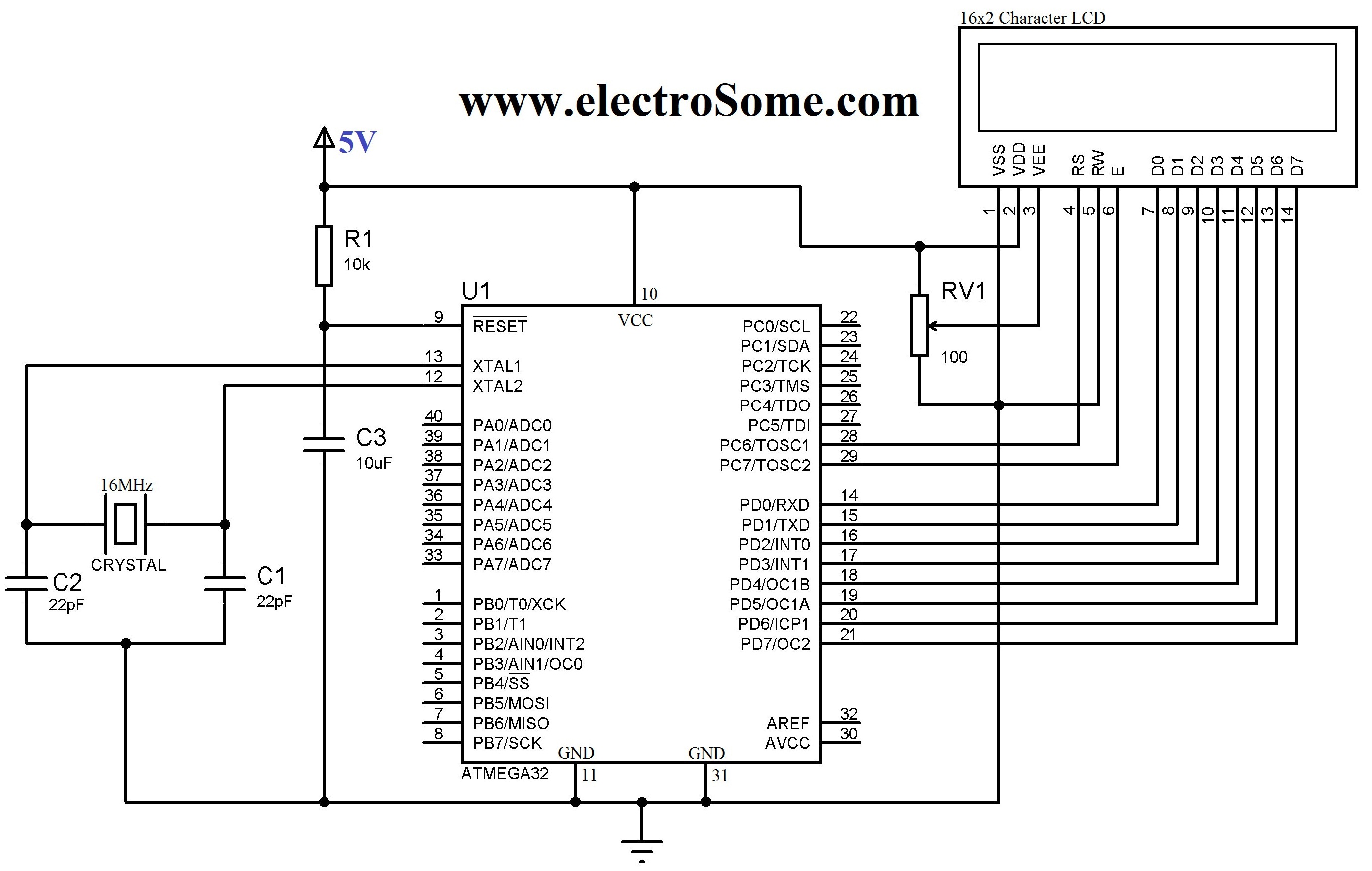
An LCD (Liquid Crystal Display) is a widely used electronic display found in devices such as calculators, laptops, tablets, and mobile phones. The 16G-2 character LCD module is a fundamental component frequently utilized by electronics enthusiasts and integrated into...
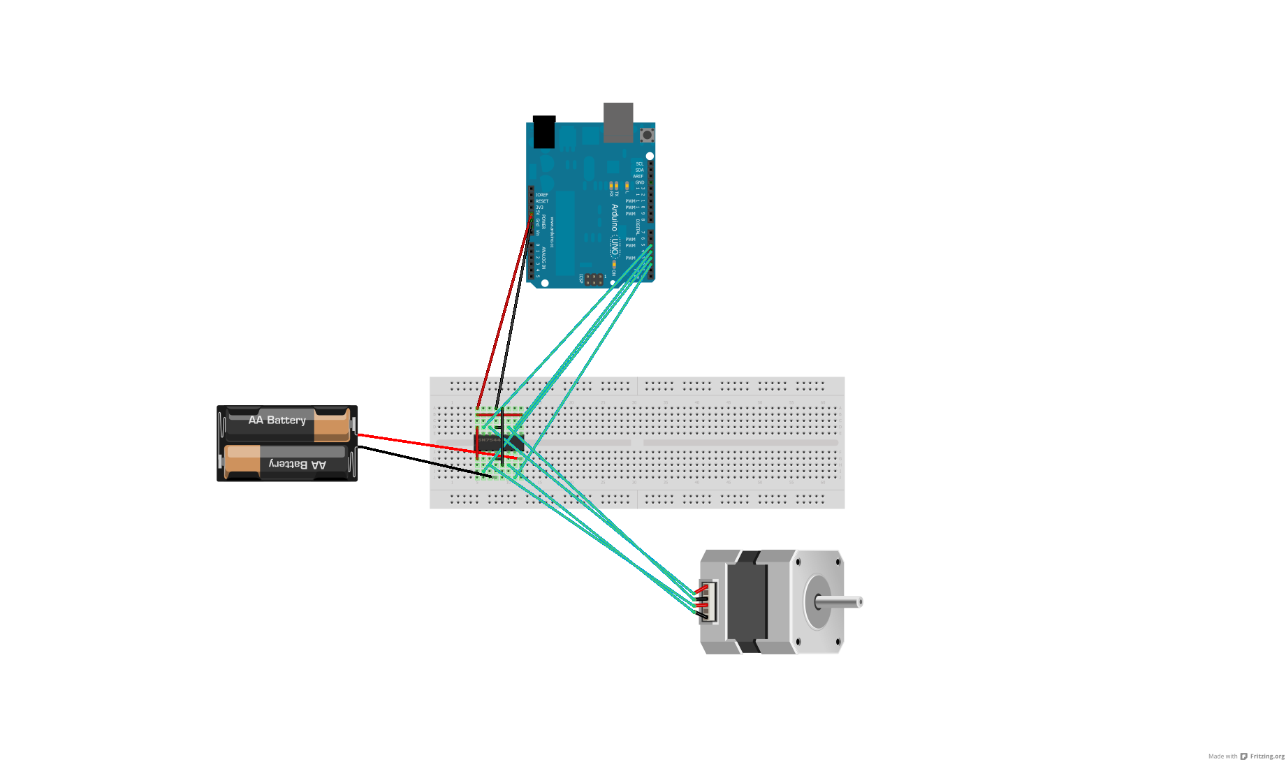
After conducting some research, it was found that voltage can be adjusted using either a voltage regulator chip or resistors. Several scenarios require reducing the voltage for motors, prompting a question about the appropriate method for each application. An...