
Network Theory
The discussion then transitions to a 10-watt audio amplifier featuring bass boost capabilities. While initially appearing complex, the focus will begin with a simplified class of circuit diagrams composed of a limited number of components, with the potential to introduce additional elements later. An explanation will be provided on how to convert any such diagram into a system of differential equations that depicts the variations in voltages and currents along the wires over time. This foundational knowledge is typically covered in introductory electrical engineering courses, particularly in the context of analog circuits, which have been largely supplanted by digital alternatives. The primary aim is not to analyze electrical circuits in isolation, but rather to emphasize how circuit diagrams serve as a visual tool for reasoning about differential equations, which can be utilized to describe various systems beyond just electrical circuits. The discussion will not extensively cover the operational principles of electrical circuits; instead, the focus will be on the mathematical framework of circuit diagrams and their broad applicability across diverse fields. An example circuit will be described, illustrating a current flowing through a closed loop of wire containing four elements: a resistor, an inductor, a capacitor, and a voltage source, such as a battery. Each component is represented by a standardized symbol, and each is associated with a numerical value. Notably, this example introduces two new features: points where wires intersect, represented as black dots, commonly referred to as nodes or vertices. The term 'vertex' begins with 'V,' just as 'voltage' does, leading to the designation of these points as voltage nodes.
The circuit's behavior can be analyzed using Kirchhoff's laws, which govern the relationships between currents and voltages in electrical networks. The application of these laws will facilitate the derivation of differential equations that describe the dynamic behavior of the circuit over time. The resulting equations can then be solved using various mathematical techniques, allowing for the prediction of circuit performance under different operating conditions. This approach underscores the versatility of circuit diagrams as a means of modeling not only electrical systems but also a wide array of dynamic systems encountered in other engineering domains.This quarter my graduate seminar at UCR will be about network theory. I have a few students starting work on this, so it seems like a good chance to think harder about the foundations of the subject. I`ve decided that bicategories of spans play a basic role, so I want to talk about those. If you haven`t read the series up to now, don`t worry! Noth ing I do for a while will rely on that earlier stuff. I want a fresh start. But just for a minute, I want to talk about the big picture: how the new stuff will relate to the old stuff. These come from the world of control theory and engineering ”especially electrical engineering, but also mechanical, hydraulic and other kinds of engineering.
My goal is not to tour different formalisms, but to integrate them into a single framework, so we can easily take ideas and theorems from one discipline and apply them to another. For example, in Part 16 we saw that a special class of Markov processes can also be seen as a special class of circuit diagrams: namely, electrical circuits made of resistors.
Also, in Part 17 we saw that stochastic Petri nets and stochastic reaction networks are just two different ways of talking about the same thing. This allows us to take results from chemistry ”where they like stochastic reaction networks, which they call chemical reaction networks` ”and apply them to epidemiology, where they like stochastic Petri nets, which they call compartmental models`.
As you can see, fighting through the thicket of terminology is half the battle here! The problem is that people in different applied subjects keep reinventing the same mathematics, using terminologies specific to their own interests making it harder to see how generally applicable their work actually is. But we can`t blame them for doing this. It`s the job of mathematicians to step in, learn all this stuff, and extract the general ideas. We can see a similar thing happening when writing was invented in ancient Mesopotamia, around 3000 BC.
Different trades invented their own numbering systems! A base-60 system, the S system, was used to count most discrete objects, such as sheep or people. But for rations` such as cheese or fish, they used a base 120 system, the B system. Another system, the E system, was used to measure quantities of grain. There were about a dozen such systems! Only later did they get standardized. This is a 10-watt audio amplifier with bass boost. It looks quite intimidating. But I`ll start with a simple class of circuit diagrams, made of just a few kinds of parts: and maybe some others later on. I`ll explain how you can translate any such diagram into a system of differential equations that describes how the voltages and currents along the wires change with time.
This is something you`d learn in a basic course on electrical engineering, at least back in the old days before analogue circuits had been largely replaced by digital ones. But my goal is different. I`m not mainly interested in electrical circuits per se: to me the important thing is how circuit diagrams provide a pictorial way of reasoning about differential equations and how we can use the differential equations to describe many kinds of systems, not just electrical circuits.
So, I won`t spend much time explaining why electrical circuits do what they do ”see the links for that. I`ll focus on the math of circuit diagrams, and how they apply to many different subjects, not just electrical circuits.
This describes a current flowing around a loop of wire with 4 elements on it: a resistor, an inductor, a capacitor, and a voltage source ”for example, a battery. Each of these elements is designated by a cute symbol, and each has a real number associated to it: This example has two new features.
First, it has places where wires meet, drawn as black dots. These dots are often called nodes, or sometimes vertices. Since vertex` starts with V and so does voltage`, let`s call the 🔗 External reference
Related Circuits
This application note provides a concise overview of power amplifier theory and presents simulation results that offer insights into the operation of the power amplifier across all of MAXIM's LFRF transmitters and transceivers. Power amplifiers are critical components in communication...
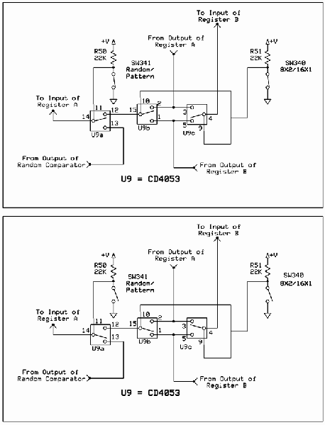
The circuit involves Clock and Load functions, with the Load function being described first. The component U5, a CD4013, is responsible for executing the load function by determining whether the shift register integrated circuits (ICs) operate in parallel or...
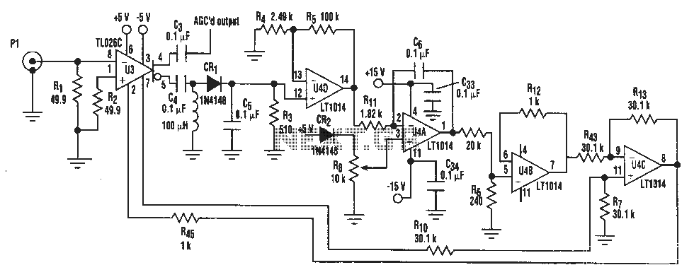
A simple IF AGC signal with a wide dynamic range and excellent linearity characteristics may be composed of two chips: the TL026C T1 voltage control amplifier IC and the LT1014 (or any other similar basic quad op amp device). The...
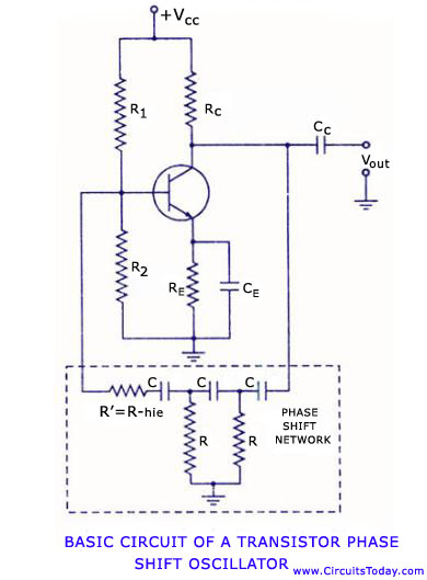
Transistor RC phase shift oscillator. RC phase shift oscillator using operational amplifier. RC phase shift network. Theory and working principle. Circuit diagram. The transistor RC phase shift oscillator is a type of electronic oscillator that generates sine wave signals. This...
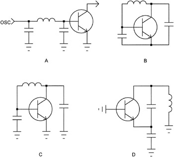
The open-loop concept of oscillator design is often met with considerable skepticism by engineers familiar with classic oscillator terminology. For clarity, consider Figure 2-4A, where the oscillator cascade is illustrated with only the RF components. The circuit is then...

A 3D enhancement is required to achieve a fully three-dimensional sound experience for most stereo multimedia products. Typically, simple phase-delay circuits are utilized to create a widening effect on the perceived sound field. However, this approach can lead to...
Warning: include(partials/cookie-banner.php): Failed to open stream: Permission denied in /var/www/html/nextgr/view-circuit.php on line 713
Warning: include(): Failed opening 'partials/cookie-banner.php' for inclusion (include_path='.:/usr/share/php') in /var/www/html/nextgr/view-circuit.php on line 713