
Newb question on 12AU7 gain stage

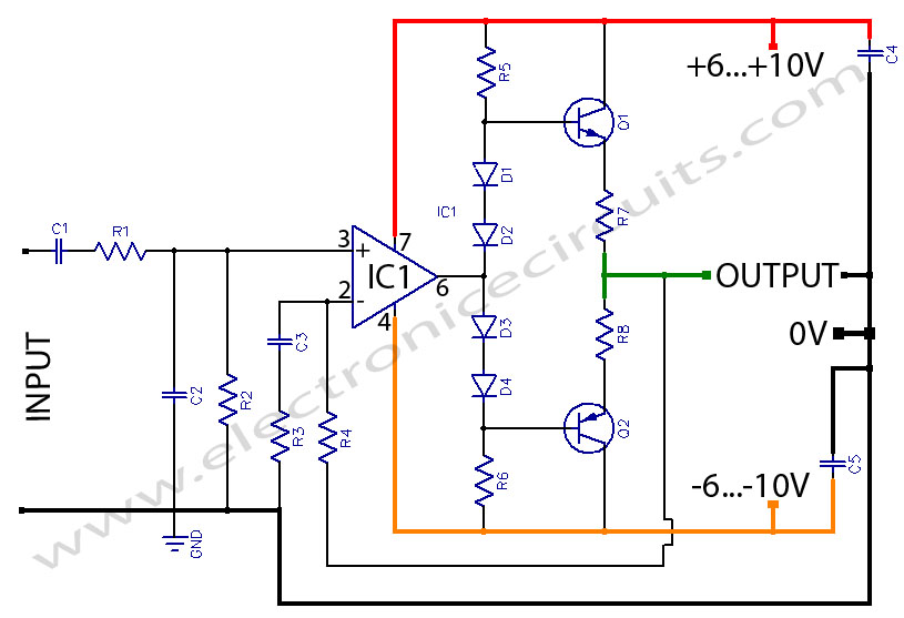
The gain stage circuit designed using Decware's Zkit4 is intended to provide impedance matching and signal buffering for the LM3875 gain clone amplifier. This configuration is beneficial as it isolates the input source from the load, ensuring that the signal integrity is maintained while driving the power amplifier.
The Zkit4 typically consists of a simple transistor-based amplifier configuration, which may include components such as resistors, capacitors, and transistors arranged to provide the desired gain characteristics. The output of this gain stage can be connected directly to the input of the LM3875, which is a high-performance audio power amplifier capable of delivering substantial output power with low distortion.
In this setup, the gain stage will enhance the input signal, allowing the LM3875 to operate effectively without being affected by the source impedance. The design of the gain stage should consider factors such as bandwidth, gain, and noise performance to ensure that the overall audio quality is preserved. Additionally, proper power supply decoupling and grounding techniques should be employed to minimize any potential interference and maintain a clean signal path.
To implement this system, it is essential to select appropriate component values for the gain stage to achieve the desired gain and frequency response. The circuit layout should also be optimized for minimal signal degradation, which may involve careful routing of traces, especially in high-frequency applications. By following these guidelines, the gain stage will effectively function as a buffer, enhancing the performance of the LM3875 gain clone amplifier.Hello Bottleheads, I am building this gain stage from Decware`s Zkit4 to use as a buffer in front of an LM3875 gain clone. The chip amp has plenty of.. 🔗 External reference
Related Circuits
The MSK4204RH is a radiation-hardened complete H-Bridge microcircuit designed for use in DC brushed motor control applications or Class D switch-mode amplification in space or other harsh operating environments. The internal components have been selected to withstand a total...
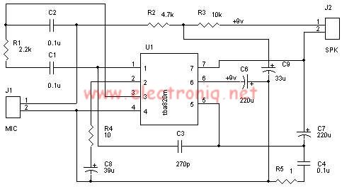
A very simple audio amplifier circuit can be designed using the TBA820M audio amplifier integrated circuit with just a few electronic components. This audio amplifier project features a high gain that allows for the detection of sounds underwater. The...
Automatic Gain Control (AGC) is a circuit design that maintains a consistent level of amplification for sound or radio frequency signals. If the signal is too low, the AGC increases the gain to ensure the output remains at a...
A cathode follower based on the 6BL7 or 6BX7 is ideal for output. I used a mu-follower circuit with no feedback, a 12SN7 as the gain stage, and a 6BL7 as the cathode follower/current source. You might argue that...
Headphone Amplifier or Pre-Amplifier Output Stage. This 1-watt amplifier is ideally suited for use as a driver for low-impedance headphones. The headphone amplifier circuit is designed to provide an amplified audio signal to drive low-impedance headphones effectively. Operating at a...
A simple and effective antenna amplifier can be built using the provided circuit diagram. This amplifier is designed for the frequency range of 35 kHz to 150 MHz. It utilizes transistors, offering a low non-linearity of 3 dB and...