
Ni-cad discharge limiter
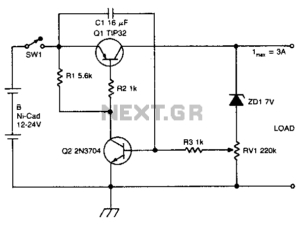
The circuit operates as a voltage monitoring and disconnect mechanism to protect the battery from excessive discharge. Initially, when the output voltage is above the threshold established by RV1, the circuit allows current to flow from the battery to the load, ensuring proper operation. The charging of capacitor C1 through resistor R1 is critical, as it provides the necessary time constant for the circuit to respond to voltage changes without immediate fluctuations.
Transistor Q2 acts as a sensing element, monitoring the output voltage. When the voltage exceeds the set point, Q2 remains in the on state, allowing current to pass through to Q1. This configuration keeps Q1 activated, thereby maintaining the connection between the battery and the load. Resistor R2 plays a crucial role in controlling the base current of Q1, ensuring that it operates within safe limits and does not draw excessive current from the battery.
As the output voltage declines and reaches the threshold voltage defined by RV1, Q2 turns off, which subsequently causes Q1 to turn off as well. This action effectively disconnects the load from the battery, preventing further discharge and protecting the battery from damage due to over-discharge conditions. This circuit is particularly useful in battery-powered applications where maintaining battery health is essential for longevity and performance.
The design of this circuit can be optimized by selecting appropriate values for R1, R2, and RV1 to ensure a quick response time while minimizing power loss. Additionally, the choice of transistors Q1 and Q2 should reflect the current requirements of the load and the characteristics of the battery being used, providing a reliable solution for battery management in electronic devices.The circuit disconnects the battery from the load when output voltage falls below a preset level. Cl charges through R1 and turns on Q2. Collector current flows through R2 turning Ql on and battery is connected to the load When the output voltage falls below a point set by RV1, Q2 turns off, Ql turns off and further discharge of the battery is prevented. 🔗 External reference
Related Circuits
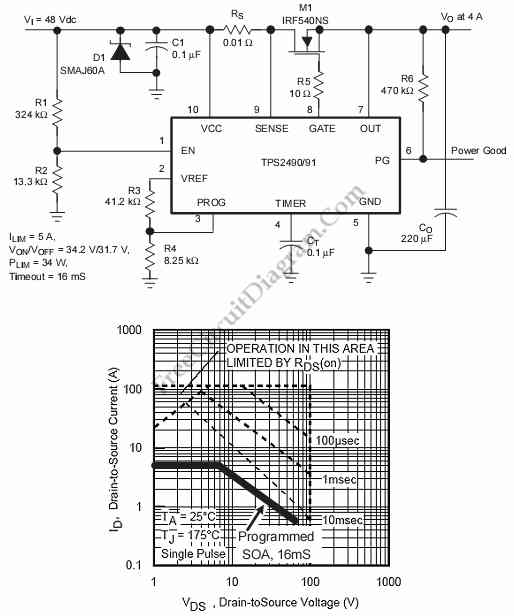
This is a positive high-voltage hot swap controller circuit with a power limiter. This circuit utilizes the TPS2491 or TPS2490, as both of them have specific features. The positive high-voltage hot swap controller circuit is designed to safely connect and...
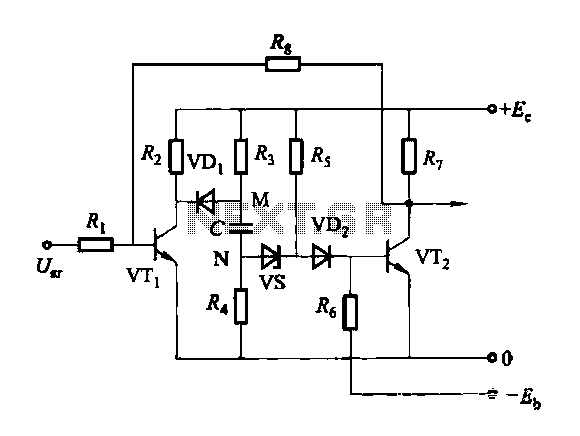
Discharge before memory circuit. Before the memory circuit is activated, a delay reset circuit is required. When the input signal triggers an action, timing begins, and after a specified delay, the circuit reverts to its original state. During this...
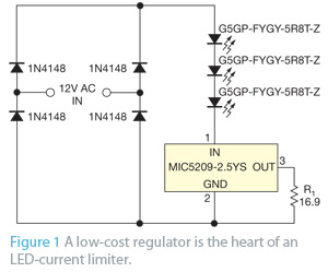
When an application does not require PWM (pulse-width-modulated) dimming or controlled frequency operation, the primary concern may be preventing excessive current that could damage or destroy LEDs. A simple LED current limiter can be created using a common low-dropout...
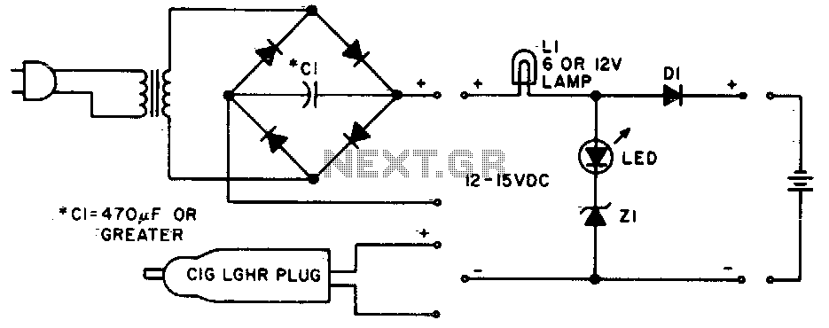
Lamp LI will glow brightly while the LED remains off when the battery is low and charging. Conversely, the LED will illuminate brightly, and the light bulb will be dim when the battery is nearly charged. Lamp LI should...
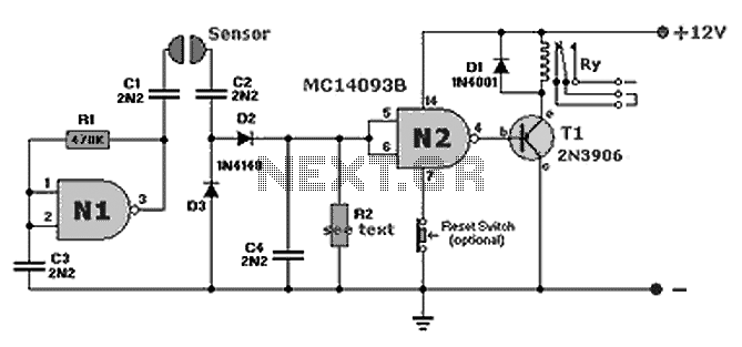
A compact fluid (water) sensor circuit that activates a relay for various applications. Additionally, a printed circuit board (PCB) is not necessary due to the small size of the circuit. The fluid sensor circuit is designed to detect the presence...
The circuit was designed to provide an indication before a 12 V lead-acid battery reaches a discharged state using an LM723 voltage regulator and a positive NPN standard voltage. The circuit utilizes the LM723 voltage regulator, which is well-suited for...