
LED current limiter accepts ac or dc
The described circuit effectively limits the current supplied to the LED array, ensuring the longevity and reliability of the LEDs in landscape lighting applications. The use of a low-dropout linear regulator, specifically the MIC5209-2.5V, is advantageous as it maintains a stable output voltage while minimizing power loss. The design allows for flexibility in terms of input voltage, making it adaptable to various landscape lighting setups.
The selection of components, such as the warm-white LEDs and rectifier diodes, ensures cost-effectiveness without compromising performance. The calculated values for the resistor R1 are critical for determining the appropriate LED string current, which is necessary for achieving the desired brightness while preventing thermal overload.
In practical applications, the circuit can be further enhanced by incorporating additional features such as thermal protection or overcurrent protection to safeguard the LEDs and the regulator. Furthermore, ensuring proper heat dissipation through adequate thermal management techniques, such as heat sinks or proper ventilation, can extend the operational life of the components involved.
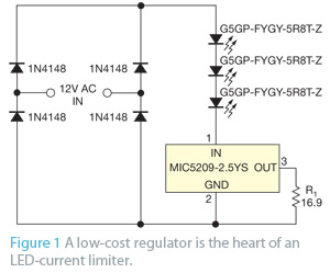
In conclusion, this LED current limiter circuit presents a practical solution for landscape lighting systems, providing a reliable and efficient means of controlling LED current while accommodating various input conditions.When your application requires no PWM (pulse-width-modulated) dimming or controlled frequency operation, your primary concern may be that too much current could damage or destroy your LEDs. In this case, you can make a simple LED-current limiter from a common low-dropoutlinear regulator. The circuit in Figure 1 is an LED light bulb for a landscape-lighting system. Landscape lighting typically operates from 12V ac, and peak voltage is approximately 17V. Because the regulator is in series with the LED string, the LED-string current equals the regulator`s output current. The circuit uses reasonably priced, 150-mA, warm-white LEDs; low-cost rectifier diodes; and Micrel `s 2.
5V MIC5209-2. 5YS regulator (Figure 1). The regulator must source at least the required LED current and handle the peak input voltage minus the drop across two of the four rectifier diodes and the drop across the LEDs. Selecting a regulator with the lowest possible output and dropout voltages lets LED current flow for a larger portion of each ac cycle, and it reduces the power requirement of current-setting resistor R1.
As output and dropout voltages decrease, cost increases. The regulator sees the peak voltage at approximately 5. 1V and dissipates approximately 0. 2W. The MIC5209-2. 5YS` output voltage regulates to 2. 5V between its output and ground. R1 sets the LED-string current using R1=(2. 5/ ILED), where ILED is the LED-string current. With a value of 16. 9 © for R1, the string current is 148 mA. The circuit has slightly more than 2. 5W peak dissipation. With an ac input, the current flows only about half the time, so the average power dissipation is approximately 1. 26W. You can easily modify the circuit to accept almost any input voltage. Simply change the number of LEDs and make sure that the rectifier diodes can handle the reverse voltage.
Add or subtract one LED for each 3. 33V increase or decrease in peak input voltage. Don`t use LEDs for the rectifier diodes to get more light output because LEDs don`t have sufficient reverse-breakdown voltage and will fail. The input bridge accepts either ac or dc and negates the need to worry about the polarity of a dc input.
🔗 External reference
Related Circuits
An output of 4 mA to 20 mA that is linearly proportional to the input voltage is provided by the current transmitter. Line rejection is included. The current transmitter operates within a specified range, providing an output current that is...
This schematic uses the 555 timer and the 4017 IC to drive 3 LED, to simulate the trafic lights. More: All diodes are iN4148. The circuit is operated with 9 volt battery or with a simple 12V battery or...
It may seem that due to the numerous flashlight projects undertaken, there is a significant collection of lights. The inductor can be altered to set the current level, but the total current fluctuates with the battery supply, decreasing as...
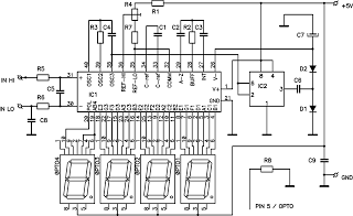
This circuit is a digital voltmeter with an LED display, ideal for measuring the output voltage of a DC power supply. It features a 3.5-digit LED display with a negative voltage indicator and measures DC voltages from 0 to...
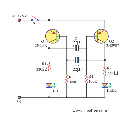
This circuit operates as a free-running multivibrator, resembling a flip-flop. It continuously oscillates on its own. The transistors Q1 and Q2 are PNP types, commonly used models include the 2N3906 and 2N2907. Resistors R1 and R2 limit the current...
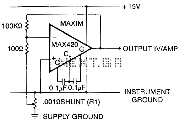
This circuit measures the power supply current of a circuit without using a current shunt resistor: R1 is only 3 cm of #20 gauge copper wire. A length of the power distribution wiring can be used for R1. The...
Warning: include(partials/cookie-banner.php): Failed to open stream: Permission denied in /var/www/html/nextgr/view-circuit.php on line 713
Warning: include(): Failed opening 'partials/cookie-banner.php' for inclusion (include_path='.:/usr/share/php') in /var/www/html/nextgr/view-circuit.php on line 713