
nicad battery charger uses
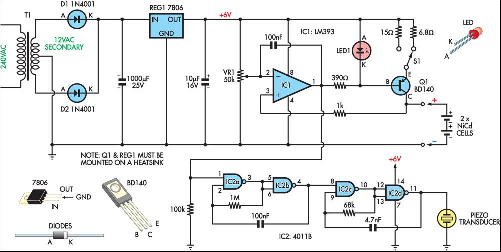
The circuit design is centered around a dual charging system, allowing for flexibility in charging rates suited for different battery conditions. The incorporation of a 12VAC center-tapped transformer ensures that the circuit can effectively convert AC voltage to a usable DC voltage through the rectification process, with the rectifier diodes D1 and D2 playing a vital role in this conversion. The 1000µF filter capacitor smooths out the rectified voltage, providing a stable input for the voltage regulator.
The 7806 voltage regulator is critical in maintaining a consistent 6V output, which is essential for the proper operation of the constant current source formed by Q1 and LED1. The choice of using a red LED in conjunction with Q1 serves a dual purpose: it not only provides visual feedback but also plays a role in establishing the required voltage drop for the constant current operation.
The variable resistor VR1 allows for fine-tuning of the cutoff voltage, ensuring that the circuit can be adjusted to accommodate variations in battery chemistry or capacity. The LM393 comparator is an effective choice for monitoring the battery voltage, providing a reliable means of determining when to cease charging, thus preventing overcharging and potential battery damage.
The integration of the NAND gates to create oscillators adds an auditory feedback mechanism, which is crucial for user awareness regarding the charging status. The pulsed tone from the piezo transducer serves as an alert that the charging process is complete, enhancing user interaction with the device.
Overall, this circuit exemplifies a well-thought-out design that prioritizes safety and efficiency in charging NiCad batteries, with multiple features that enhance functionality and user experience.This circuit charges two NiCad cells with a constant current and features dual charging rates, voltage cutoff and an audible alarm. The circuit is powered by a 12VAC centre-tapped mains transformer, together with two rectifier diodes (D1 & D2) and a 1000mF filter capacitor.
A 7806 3-terminal regulator is used to generate a 6V rail for the remainde r of the circuit. Transistor Q1 and LED1 constitute a basic constant-current source. The forward voltage of the red LED (about 1. 5V) minus Q1`s base-emitter voltage (about 0. 6V) appears across the 6. 8W or 15W emitter resistors, depending on the position of S1. With a 15W resistance in the emitter circuit, the charging current is about 60mA, whereas with 6. 8W it is about 130mA. This is sufficient to charge 600mAH "AA" cells in 14 hours and five hours, respectively. An LM393 voltage comparator (IC1) is used for the voltage cutoff function. Its inverting input is set to 2. 9V (nominal) via trimpot VR1, while the non-inverting input senses battery voltage. This means that while the cells are being charged, the output transistor (in the LM393) is switched on, also switching on Q1 and enabling the current source. Once the cells are charged to approximately 80% or more of capacity, their terminal voltages will exceed 1.
45V, so the voltage at the non-inverting input (pin 3) of IC1 will exceed the reference voltage on the inverting input (pin 2). This causes IC1`s output to switch off, in turn switching Q1 off and disabling the current source. To prevent rapid switching action around the voltage cutoff point, a 100nF capacitor provides feedback between the output and inverting input of the comparator.
Four NAND gates are used to build two simple oscillators of different frequencies. When cascaded together, the result is a pulsed tone from the piezo transducer to indicate charge completion. Absolute terminal voltage is not always a reliable indicator of Nicad battery charge state. Importantly, batteries should never be charged for longer than the manufacturer`s specified period. 🔗 External reference
Related Circuits
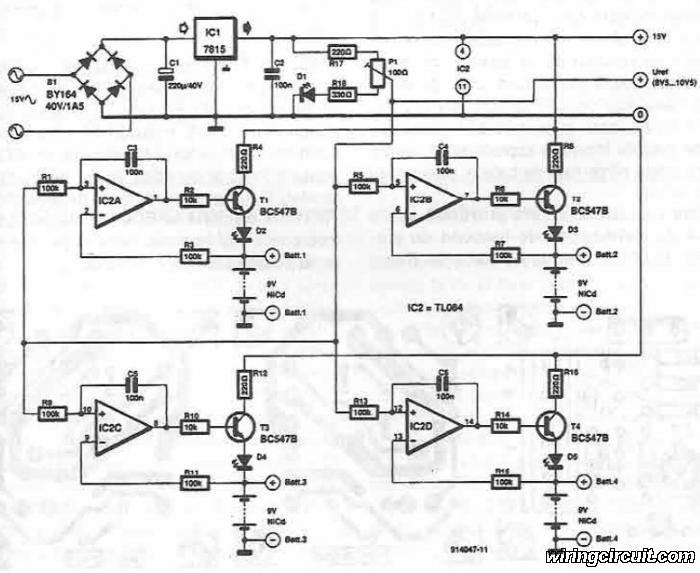
This electronic circuit diagram facilitates the design of a straightforward charging circuit for NiCd batteries. The charger is capable of simultaneously charging four 9V NiCd batteries, with the voltage being adjustable via a potentiometer labeled P1. The described circuit operates...
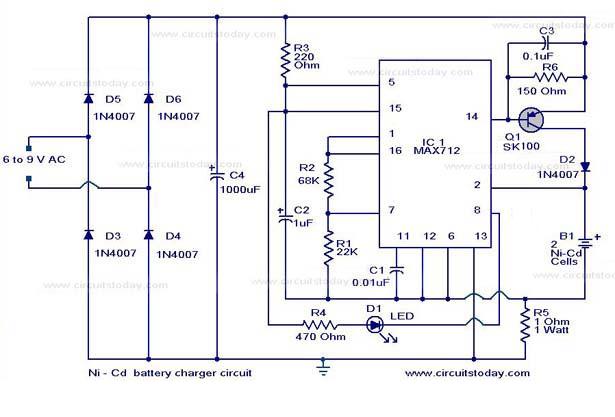
The following circuit illustrates a super fast Ni-Cd battery charger. It is based on the IC MAX 712 and is designed to charge a Ni-Cd battery at a rate of 300 mA. The circuit utilizes the MAX 712 integrated circuit,...
Widely available AA NiMH battery chargers are on the market, including those packaged to charge various battery types such as NiCd and NiCad. This project features a battery charger designed for two AA NiMH or NiCd cells of any...
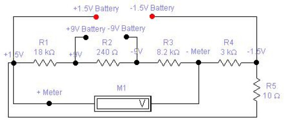
The circuit diagram of a DC battery tester designed by Matthew B. This circuit can measure DC batteries ranging from 1.5V to 9V. Component Parts List: R1 = 18K Ohm, R2 = 240 Ohm, R3 = 8.2K Ohm, R4...
The circuit is designed for charging NiMH batteries using the MAX712 integrated circuit (IC), which provides all necessary functionalities for controlled charging. The schematic of the charger is centered around IC1, the MAX712 from Maxim, which comes in a...
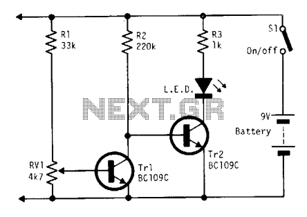
Continuously monitors battery voltage during use and consumes only about 250 microamperes until the end point is reached. Near the end point, transistor Tr1 turns off, allowing transistor Tr2 to illuminate the LED, which increases current drain further, leading...