
NiMH Battery Chargers
The described AA NiMH battery charger circuit is designed to efficiently charge two identical NiMH or NiCd cells. The design operates at a charging current of approximately 470 mA, which is suitable for a variety of AA-sized rechargeable batteries. The USB interface serves as the power source, providing a standardized 5V output, which is readily available from most modern electronic devices, such as computers and USB wall adapters.
The charger is capable of charging batteries with different capacities, such as 700mAh, 1500mAh, and 2500mAh, within specified time frames of 1.5, 3.5, and 5.5 hours, respectively. This flexibility allows users to charge batteries depending on their specific needs and usage patterns.
An important feature of this charger is the automatic cutoff circuit, which monitors the temperature of the cells during charging. This safety mechanism prevents overcharging, which can lead to battery damage or reduced lifespan. Once the charger detects that the cells have reached full charge, it will terminate the charging process, allowing the batteries to remain in the charger without risk of damage.
The schematic includes components such as a microcontroller or dedicated charging IC that manages the charging process, a temperature sensor for cutoff activation, and necessary protection circuitry to ensure safe operation. Additionally, the circuit may incorporate indicators, such as LEDs, to signal the charging status, providing visual feedback to the user.
Overall, this battery charger design leverages the ubiquitous USB power standard, ensuring compatibility and convenience while maintaining safety and efficiency in charging NiMH and NiCd batteries.Widely available AA NiMH battery chargers are in the market, even those already in a single package that can be used to charge other battery types such as NiCd, NiCad, and other types. Battery charger in this project is designed for two AA NiMH or NiCd cells of any capacity (as long as they are the same) at approximately 470 mA which will use the
USB port as power. This battery charger will charge 700mAh NiCds in about 1. 5 hours, 1500mAh NiMHs in about 3. 5 hours, and 2500mAh NiMHs in about 5. 5 hours. Charger incorporates the automatic bill cut-off circuit based on cell temperature, and the cells can be left in the charger indefinitely after the cut-off. The NiMH Battery charger schematic can be viewed as follows: As important to know that any USB port can supply 5V up to 500mA.
USB standard specifies that the device cannot use more than 100mA until it has negotiated the right to use the 500mA, but apparently no USB ports enforce that requirement. This makes the USB port is a convenient source of power for devices like this charger. 🔗 External reference
Related Circuits
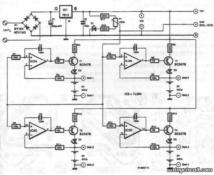
This electronic circuit diagram facilitates the design of a straightforward charging circuit for NiCd batteries. The charger is capable of simultaneously charging four 9V NiCd batteries, with the voltage being adjustable via a potentiometer labeled P1. The described circuit operates...
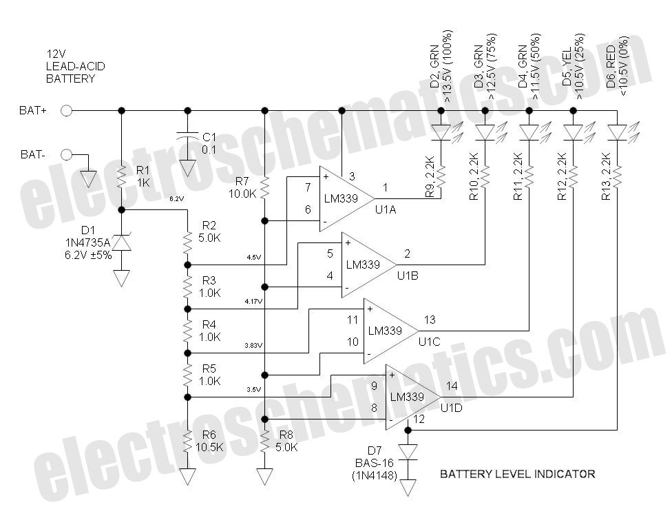
This battery level indicator features five LEDs that illuminate progressively as the voltage increases: Red indicates power connection (0%), Yellow signifies voltage greater than 10.5V (25%). The battery level indicator circuit utilizes a series of five light-emitting diodes (LEDs) to...
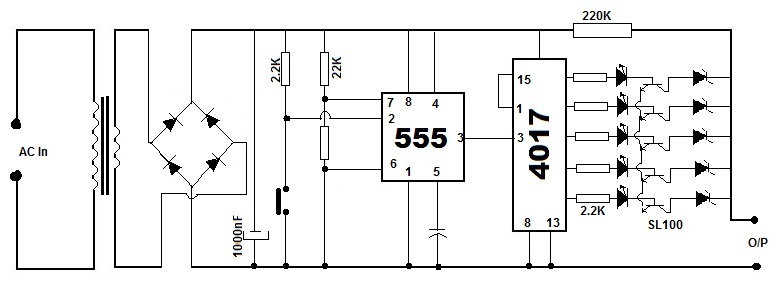
Battery eliminators are circuits that create a DC power supply from AC mains. Essentially, battery eliminator circuits consist of a step-down transformer, rectifier, and voltage regulator. A simple circuit of a multipurpose battery eliminator features various output voltage ranges...
USB Battery Charger for Lithium Ion batteries using the LM3622 is a specialized charger circuit designed to operate with power sourced from a USB connection. The current consumption of the LM3622 is limited to 400mA by a resistor (R1),...
This circuit utilizes the well-known and easily accessible LM3914 integrated circuit (IC). The IC is straightforward to operate, requiring no external voltage regulators due to its built-in voltage regulation capability, and can be powered by a variety of sources....

This circuit delivers an initial voltage of 2.5V per cell to rapidly charge a car battery. The charging current decreases as the battery charges. This circuit is designed to provide an efficient charging solution for car batteries by applying an...
Warning: include(partials/cookie-banner.php): Failed to open stream: Permission denied in /var/www/html/nextgr/view-circuit.php on line 713
Warning: include(): Failed opening 'partials/cookie-banner.php' for inclusion (include_path='.:/usr/share/php') in /var/www/html/nextgr/view-circuit.php on line 713