
Battery indicator
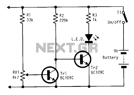
This circuit is designed to monitor battery voltage levels while ensuring minimal power consumption. The primary component, Tr1, is a transistor that operates in a low-power state, drawing approximately 250 microamperes. This low consumption is crucial for applications where battery life is a priority.
As the battery voltage approaches a predefined threshold, Tr1 ceases operation, which triggers Tr2 to activate. Tr2 is responsible for driving a low current LED diode. The LED serves not only as an indicator of the circuit's status but also increases the current draw from the battery. This additional load assists in reaching a clear and distinct turn-off point for the circuit, ensuring that the battery is not over-discharged, which could lead to damage.
The use of a low current LED diode is essential in this design, as it allows for visual feedback without significantly impacting the overall power consumption. The circuit can be applied in various battery-operated devices where monitoring battery status is critical, such as portable electronics or remote sensors.
In summary, this battery monitoring circuit effectively balances low power consumption with functionality, leveraging transistors for control and an LED for user indication, thereby enhancing the reliability and longevity of battery-powered applications.Continually monitors battery voltage during use and consumes only about 250 ? A (until the end point is reached). Near the end point Trl turns off, allowing Tr2 to illuminate the LED to increase current drain further leading to a distinct turn off point. Use a low current LED diode. 🔗 External reference
Related Circuits
A UHF indicator, or wavemeter, is a device that measures frequencies and determines the resonance frequency of an LC circuit. This device operates without the need for radiation. The oscillator is constructed using transistors T1 and T2 (two BF494),...
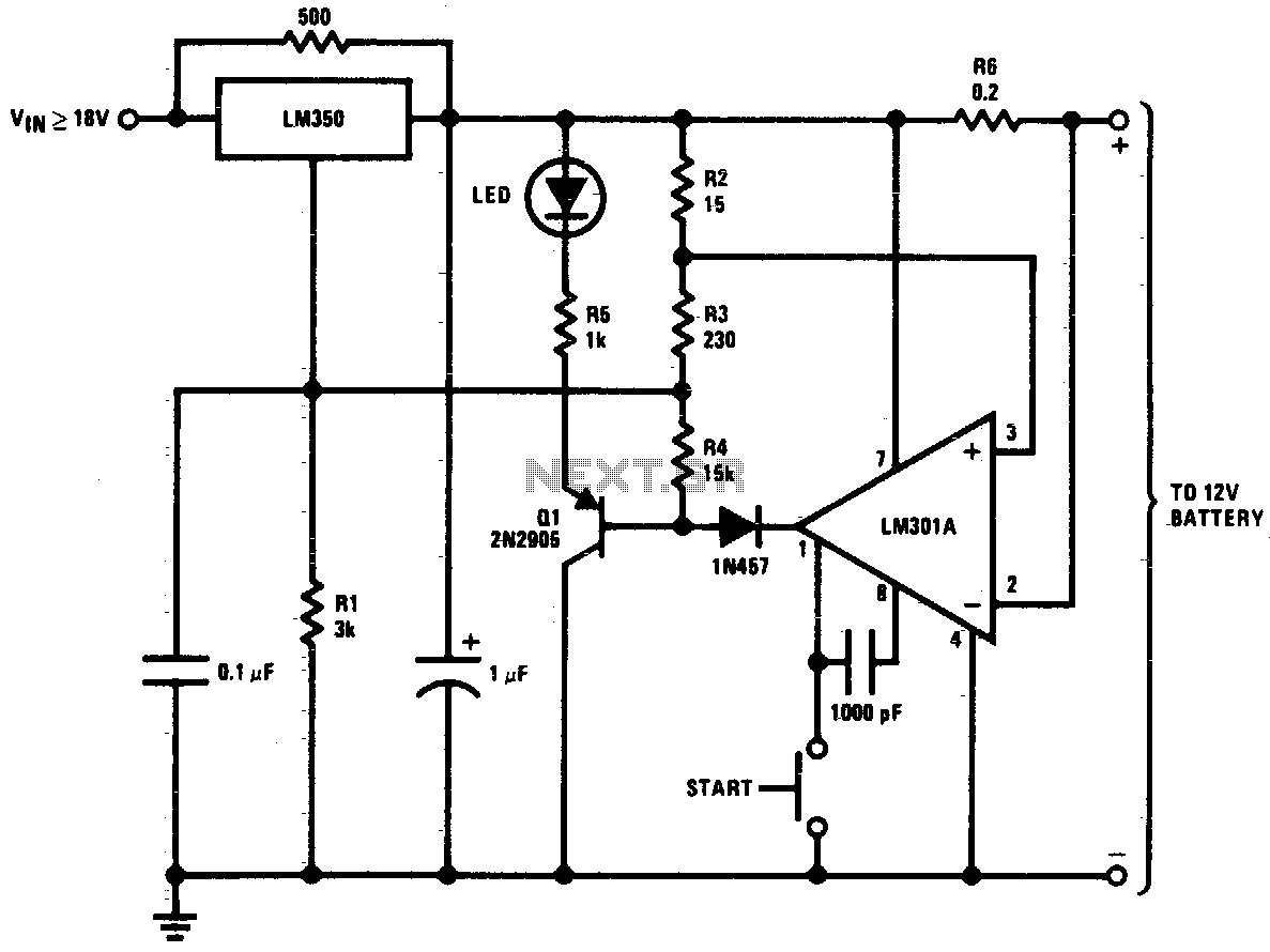
This circuit is a high-performance charger for gelled electrolyte lead-acid batteries. The charger quickly recharges the battery and automatically shuts off when it reaches full charge. Initially, the charging current is limited to 2A. As the battery voltage rises,...
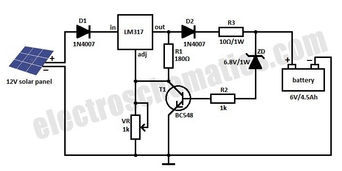
This is a solar charger circuit designed to charge Lead Acid or Ni-Cd batteries using solar energy. The circuit captures solar energy to recharge a 6-volt, 4.5 Ah rechargeable battery for various applications. It includes voltage and current regulation...
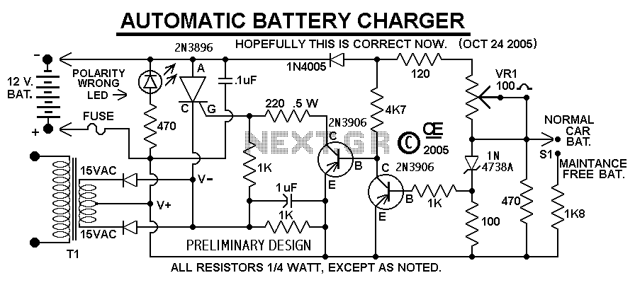
This Charger Can't be used as a Power Supply, Without having a battery in place. The Battery MUST be Connected to get power out. Note: This Charger Features a Reverse polarity Indicator. Instructions: Before plugging this charger into the...

The CMOS 4001 consists of four independent two-input NOR gates. These gates are organized into two pairs. Gates 1 and 2 are connected to form a latching circuit. When the alarm is triggered, they will latch and activate the...
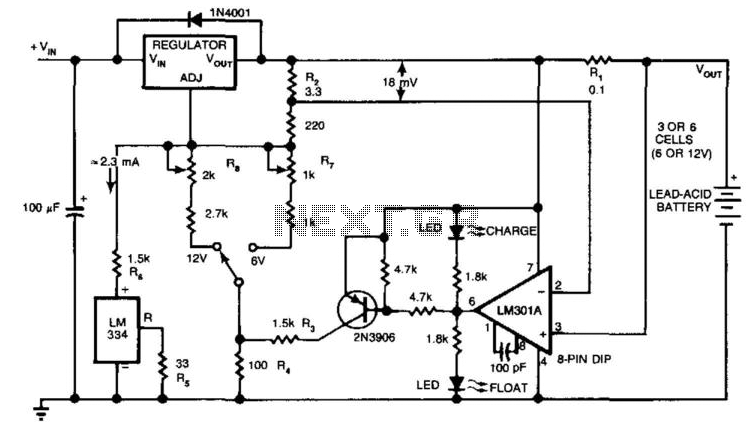
The circuit provides an initial charging voltage of 2.5 V per cell at 25°C to quickly charge a battery. The charging current decreases as the battery charges, and when the current falls to 180 mA, the charging circuit lowers...