
Traynor YBA-1 at high plate voltage
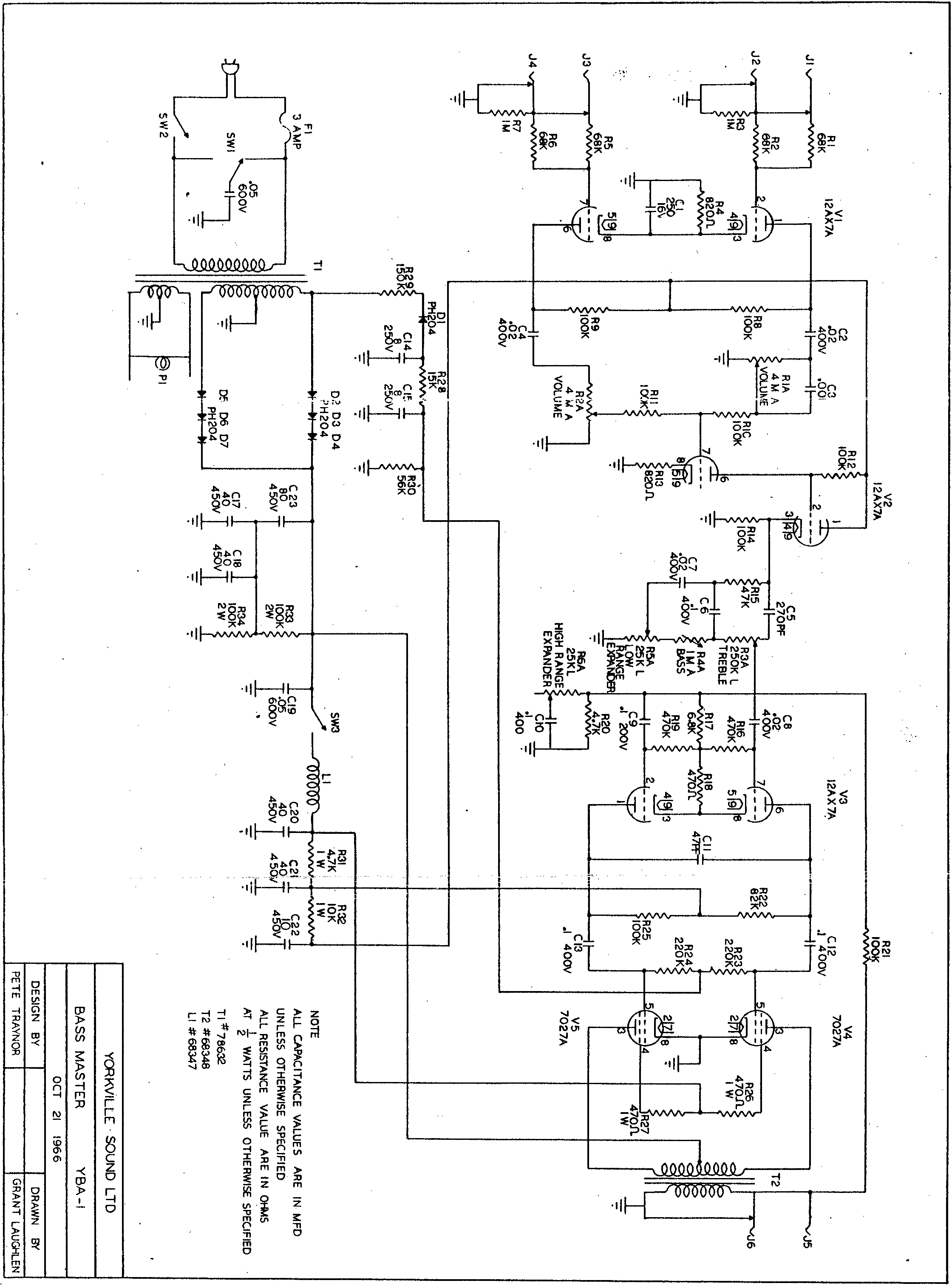
The Traynor YBA-1 amplifier circuit is a classic design that exemplifies the robust construction typical of mid-20th-century amplifiers. The circuit utilizes a push-pull configuration of 7027A tubes, which are known for their high voltage tolerance and ability to deliver substantial power output. The power transformer plays a critical role in the amplifier's performance, supplying the necessary high voltage for the plates and screens of the output tubes while also providing filament voltage to the heaters.
In this specific case, the use of the Hammond 278CX transformer, despite its higher secondary voltage rating, necessitates careful consideration of the overall circuit design and component ratings. The original design's specifications and the component tolerances must be observed to prevent potential damage to the tubes and other circuit elements. The choice to replace the screen resistors with higher wattage components is a prudent measure to mitigate the risks associated with elevated screen voltages, ensuring reliability and longevity of the output stage.
The modifications performed, including the installation of a variable bias adjustment, allow for fine-tuning of the amplifier's performance characteristics, which is particularly important given the high B+ voltage observed. The adjustment of bias current can significantly affect the amplifier's tonal qualities, efficiency, and thermal performance. The decision to operate the amplifier at a cooler bias setting is a strategic approach to manage the stress on the output tubes, especially in light of the higher than expected voltages.
Furthermore, the maintenance actions taken, such as cleaning the potentiometers and replacing old capacitors, are essential for restoring the amplifier's functionality and ensuring optimal performance. These steps are critical in vintage amplifiers, where component aging can lead to degraded performance and reliability.
In conclusion, the modifications and repairs made to the Traynor YBA-1 reflect a deep understanding of amplifier design and the importance of maintaining vintage equipment. The careful selection of components, attention to voltage ratings, and implementation of safety measures are all indicative of a thorough approach to electronics engineering within the realm of audio amplification.As some of you know, the Traynor YBA-1 is a very close derivative of the classic Bassman/JTM-45 circuit. I recently picked up a spectacularly clean `67 copy that was all original with the exception of a rather "crappy" fully reversible master volume mod and unfortunately a burnt Power Transformer.
This is the version that has the SS rectifier and choke and is exactly like the schematic that can be found here: I spent quite a bit of time trying to locate a period correct PT, with no luck. these things were built like tanks and over engineered wrt the power circuits, hence, not many really bite the bullet.
I finally ended up using the failed unit as a reference for locating a current production similar sized Hammond PT, which I found in the 278CX. Ironically, the form factor and mounting scheme was exactly alike, so all good there. Except - and this is a pretty big *except* - the secondary is wired for 800V center tapped. My calculations put the B+ at well over 500V. I have no idea what the specs are for the original, Hammond doesn`t have a clue, as these were specially produced for Traynor in the mid-60`s, and emails with Traynor came up short - apparently they don`t keep records that long either.
So off I go. The original tube chart calls for 7027A power tubes, which were rated north of 500V on the plates and 450V on the screens. So I bought some of the CP JJ 7027A`s, which are really just larger bottled 6L6GC`s (I have found out), and installed the 278CX.
While waiting on the PT to arrive I also did a bit of maintenance, 3-prong power w/death cap removal, cleaning the pots, replacing all the Electrolytics, checking the main coupling caps for DC leakage, installing a variable bias adjust pot/1-ohm 1% resistors off the cathodes, verifying and replacing key resistors that were in some cases way out of spec, etc. Typical stuff for an over 40yo amp that is all original. I also replaced the 4M Volume pots which is pretty standard mod for these YBA-1s. The PT arrived last week, I installed it, no problem. Well, ok, maybe a slight problem. If anyone is familiar with the *newer* 278CX, maybe you can offer some insight. The primary side is wired with White-Brown-Black leads for 115VAC and 125VAC connections. If you look at the spec sheet on the Hammond website, on this link at the bottom of the page: it shows that for 125VAC to use the White and Black.
There is no gray, but mine is brown. No worries, I just assumed the brown and gray are more or less interchangeable. Ironically, on the label affixed to the top of the 278CX PT, it says: I wondered about this - so after several days of trying to get in touch with someone at Hammond, I spoke to one of the engineers. He informed me that the spec sheet should be correct and for 125 mains, I should use the White-Black leads.
Unfortunately, I didn`t check before I installed it. I just assumed they knew. So I wired it up and fired it up. Started testing some voltages, with no tubes I was in the high 500`s on the B+ range, which was high but somewhat expected. However, my heaters seemed a little high. everything else checked out. So I put in the tubes. B+ dropped to 540V on the plates and 541V on the screens. Now that is HOT for a 50W amp. I checked the heaters and they are showing roughly 6. 5V, even though it`s in spec, its still seems kind of high. My wall voltage is right at 123VAC. So it made me wonder if I used the correct Primary voltage wiring scheme. I could disconnect the PT and manually check, but if anyone here has experience with this particular xfmr and knows for sure, please chime in.
Ok - still hanging in there I see. Now to the jist. As I said the Plates and Screens are running right at 540Vs. I replaced the 470 1W screen resistors with a nice pair of Ohmite 1k 5Ws that I had just to be a little safer. I biased it down really cool due to the high voltages to see how it all sounds. I am at ~31 mA (@540 Vp) which cor 🔗 External reference
Related Circuits
The Delta configuration of resistors R2, R3, and R4 is converted to a Wye (Y) configuration. This conversion is necessary because a voltage divider is typically employed in series circuits. The aim is to determine the total resistance in...
The UCD90124/A is utilized to monitor multiple voltages, some of which exceed 2.5V. Scaling circuits are implemented to prevent exceeding the 2.5V maximum on the MON inputs. The inquiry pertains to whether raw voltage values or scaled values should...
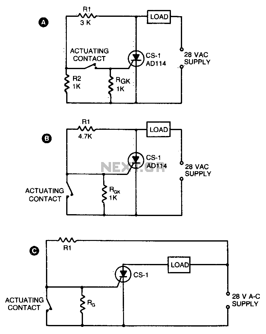
Two simple arrangements for resistive loads are shown in A and B. The circuit in A will provide load power when the actuating contact is closed, and no power when the contact is open. B provides the reverse of...
This circuit converts a positive voltage to a negative voltage, resulting in a loss of approximately 1.5 V. For instance, supplying 9 V to the circuit yields an output of -7.5 V. Additionally, this circuit can function as a...
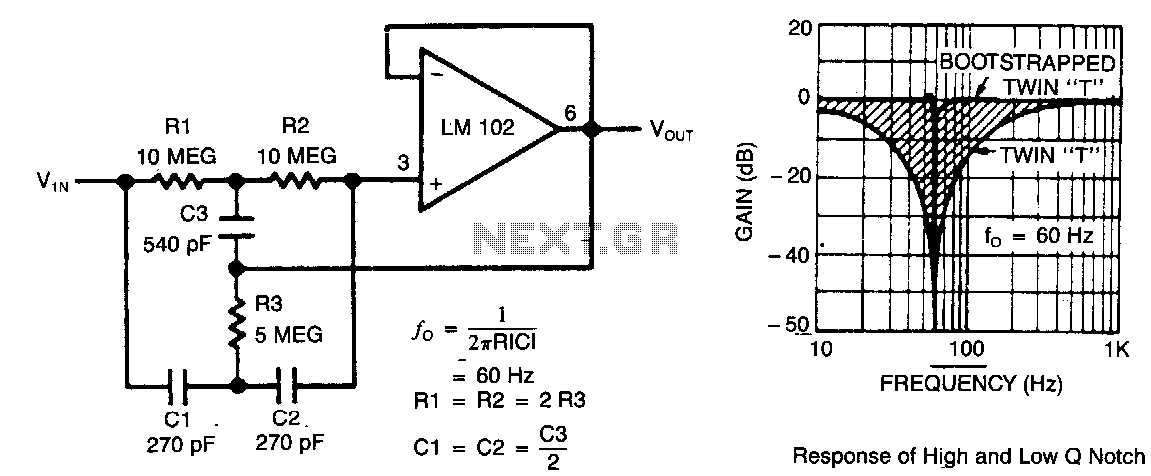
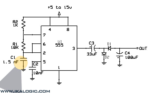
This circuit illustrates a twin-T network connected to an LM102 to form a high-Q, 60-Hz notch filter. The junction of R3 and C3, which is typically grounded, is bootstrapped to the output of the follower. Due to the low...
While the battery is charging, its voltage is measured at V. If the measured voltage is lower than the minimum threshold, the relay will be activated, connecting the charger circuit. When the battery voltage exceeds the maximum set point,...
Warning: include(partials/cookie-banner.php): Failed to open stream: Permission denied in /var/www/html/nextgr/view-circuit.php on line 713
Warning: include(): Failed opening 'partials/cookie-banner.php' for inclusion (include_path='.:/usr/share/php') in /var/www/html/nextgr/view-circuit.php on line 713