
Maximum Minimum Voltage Indicator
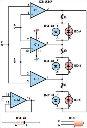
The circuit utilizes three operational amplifiers configured as voltage comparators to evaluate the input voltages at points A, B, and C. Each op-amp compares the voltage at its non-inverting input to the voltage at its inverting input, providing a binary output that indicates which input voltage is greater. The outputs of these comparators are connected to three LEDs, each representing one of the input voltages. The use of 1kΩ resistors in series with the LEDs ensures that the current flowing through the LEDs remains within safe limits, preventing potential damage due to excessive current.
In the configuration where the circuit indicates the highest voltage, the logic is such that only one LED will be illuminated at any given time, corresponding to the highest input voltage. For instance, if voltage A is the highest, LED A will light up, while the other two LEDs remain off. The operation of the circuit can be adjusted by altering the connections of the LEDs and diodes. When the diodes are reversed, the circuit switches to indicate the lowest voltage instead. This versatility allows for various applications depending on the specific requirements of the user.
Moreover, if the circuit is modified to include additional LEDs in place of the 1N4148 diodes, it can provide simultaneous indications for both the highest and lowest input voltages. This modification enhances the functionality of the circuit, making it suitable for applications where monitoring both extremes of voltage levels is essential. Overall, this circuit design is efficient and adaptable, making it a valuable tool in electronic applications that require voltage comparison and indication.This circuit indicates which of three voltages in the range from about about -4V to about +4V - at A, B and C - is the highest by lighting one of three indicator LEDs. Alternatively, it can be wired to indicate the lowest of three voltages or to indicate both the highest and lowest voltages.
Op amps IC1a, IC1b & IC1c are wired as comparators, whil e the three indicator LEDs and their series 1kO current limiting resistors are strung across the op amp outputs to implement the appropriate logic functions. For example, LED A will light only when pin 8 of IC1c is low (ie, A greater B) and pin 7 of IC1b is high (ie, A greater C).
Similarly, LED B will light only when pin 8 of IC1c is high (ie, B greater A) and pin 1 of IC1a is low (ie, B greater C). LED C works in similar fashion if the voltage at C is the highest. Note that if all the LEDs and their parallel 1N4148 diodes are reversed, the circuit will indicate the lowest of the three input voltages.
And if each 1N4148 diode is replaced by a LED, the circuit will indicate both the highest and lowest inputs. 🔗 External reference
Related Circuits
This circuit diagram is provided for those interested. It is a small circuit that takes an input of 1.5 volts and outputs 120 volts. The circuit in question is a voltage step-up converter, commonly referred to as a boost converter....
The SA9614 is an RF amplifier utilized for signal conversion and automatic laser power control (ALPC) between the CD optical pickup head and the decoding chip. The SA9614 incorporates an interface for the CD optical diode RF signal amplifier...
This circuit is designed for pulse width (time) to voltage conversion. According to the component parameters in the diagram, it can convert a pulse width of 0.1 seconds into an output voltage of 10V. When a conversion pulse is...
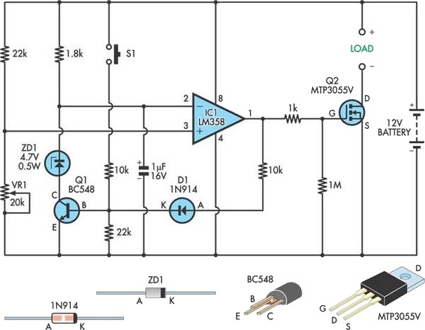
This circuit safeguards a sealed lead-acid (SLA) battery from over-discharge by disconnecting the load when the terminal voltage drops below a specified threshold. The operation involves deriving a sample of the battery voltage through a voltage divider composed of...
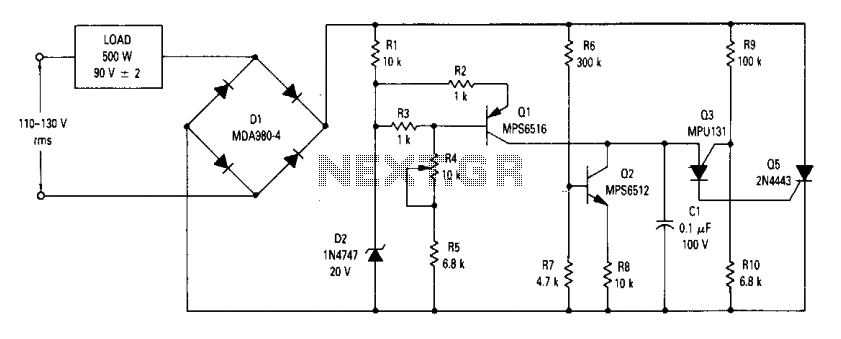
The circuit is an open-loop RMS voltage regulator designed to deliver 500 watts of power at 90 V RMS, maintaining good regulation within an input voltage range of 110-130 V RMS. When the input voltage is applied, capacitor C1...
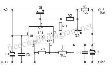
The circuit diagram of the variable regulator utilizes the IC L200 as a regulator for both voltage and current. This integrated circuit is produced by the company. The L200 is a versatile adjustable voltage and current regulator that can deliver...