
NiCd Battery Charger

The charger circuit is designed to efficiently manage the charging process for batteries, ensuring that the LED indicator provides a visual cue for the charging status. The main components include a mains adapter, which converts AC voltage from the power outlet to a suitable DC voltage for charging. The circuit employs two resistors, where R1 is critical for determining the charging current and voltage drop necessary for LED operation, while the second resistor can be used for additional current limiting or voltage division depending on the specific application.
The charging current is carefully set to one-quarter of the battery's capacity to prevent overheating and excessive wear on the battery, while still allowing for a slight overcharge that can enhance battery life. The charging duration is optimized to between 4 to 5 hours, making this circuit suitable for various rechargeable battery applications.
The calculation method for R1 ensures that the charger adapts to different battery specifications by requiring knowledge of both the nominal voltage and capacity of the battery being charged. The output voltage setting of the mains adapter is crucial, as it must accommodate the voltage drop across R1 while providing enough potential to charge the battery effectively. The requirement that the adapter supply at least half of the battery capacity ensures that the charger can operate efficiently without risking damage to the adapter or the battery.
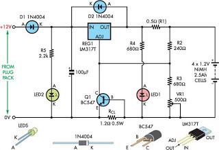
In practical scenarios, resistor values can be selected from the E12 series to ensure compatibility and availability. The design's flexibility in accommodating different battery capacities and voltages makes it suitable for a range of applications, from consumer electronics to specialized equipment requiring reliable charging solutions. Overall, this charger design exemplifies a straightforward yet effective approach to battery management, balancing safety, efficiency, and usability.The design of the charger is similar to that of many commercially available chargers. The charger consists of a mains adaptor, two resistors and a light-emitting diode (LED). In practical use, this kind of charger is perfectly all right. Resistor R1 serves two functions: it establishes the correct charging current and it drops sufficient voltage t o light the diode. This means that the LED lights only when a charging current flows into the battery. The charging current is about 1/4 of the battery capacity, which allows a slight overcharging, and yet the charging cycle is not too long (4 5 hours). The value of the resistors may be calculated as follows, for which the nominal e. m. f. and the capacity of the battery must be known. Adjust the output of the mains adaptor to 1. 17 times the nominal battery voltage plus 3. 3 V, which is the potential across R1. Note that the adaptor must be capable of supplying a current of not less than half the battery capacity.
The value of R1 in ohms is equal to 3. 3 divided by 1/4 of the battery capacity. The value of the resistors for various battery voltages is given in the Table. The battery capacity is taken as 1 Ah. The rating of R1 should be 5 W. If the battery to be charged has a different capacity, the theoretical value of R1 in the table must be divided by the battery capacity. Its actual value is the nearest one in the E12 series. For instance, if a 6 V battery with a nominal capacity of 600 mAh is to be charged, the value of R1 must be 20/0.
6 = 33R. 🔗 External reference
Related Circuits
This simple charger utilizes a single transistor as a constant current source. The voltage across the pair of 1N4148 diodes biases the base of the BD140 medium power transistor. The circuit operates by employing the BD140 transistor to regulate the charging...
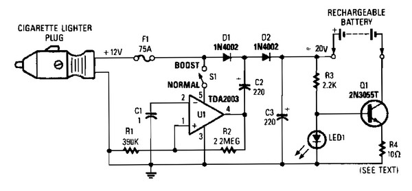
V1 creates a square wave oscillator, while D1 and D2 couple this square wave to a 12-V battery, raising the voltage to over 20 VDC. If this elevated voltage is not required, S1 can remain open. Q1 functions as...
This charger is designed to efficiently charge most lead-acid batteries. It provides full current until the battery's current draw decreases to 150 mA. At this point, a lower voltage is applied to complete the charging process and prevent overcharging....
This is a dry cell battery charger circuit designed to charge batteries over a period of approximately 12 hours. When powered by a 9-volt supply, the circuit is configured to accommodate AA-sized batteries. If C or D-sized batteries are...
Although not a new device, the LM317 is still a high-performance regulator. Its output voltage is essentially immune to fluctuations in load and supply voltage. The LM317 is a versatile adjustable linear voltage regulator widely used in various electronic applications....
The design of solar panel systems with a lead-acid buffer battery typically allows for battery charging even during low sunlight conditions. However, this necessitates the use of a regulator to prevent overcharging during periods of abundant sunshine. Common solutions...