
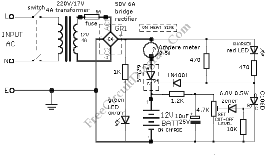
12vdc mobile battery charger
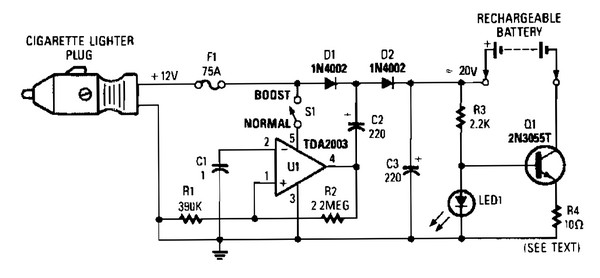
The circuit consists of several key components that work together to form an efficient mobile battery charging system. The square wave oscillator (V1) generates a periodic square wave signal, which is essential for driving the subsequent components. The output from V1 is fed into diodes D1 and D2, which rectify the AC component of the square wave, allowing for the conversion of the 12-V battery voltage into a higher DC voltage exceeding 20 VDC. This elevated voltage is particularly useful for charging applications where higher voltages are necessary.
Switch S1 provides flexibility in the design; when not needed, it can be left open, effectively bypassing the circuit that elevates the voltage. This feature allows the circuit to operate under different conditions depending on the requirements of the battery being charged.
Transistor Q1 is employed as a current regulator, a critical component that ensures the charging current is maintained at a safe level for rechargeable batteries. This regulation is crucial for preventing overcharging, which can lead to battery damage or reduced lifespan. The current regulation is achieved through feedback mechanisms that monitor the voltage across the battery and adjust the current flowing to it accordingly.
Resistor R4 plays a significant role in the circuit, as it can either be selected from a predefined table or actuated through a rotary selector switch. This selection allows for precise control over the charging current, accommodating various battery types and capacities. The ability to adjust R4 ensures that the charging process is optimized for different battery chemistries, enhancing the overall efficiency of the charger.
This schematic diagram is specifically designed for 12V DC applications, making it suitable for a range of mobile devices that require reliable battery charging solutions. The design considerations taken into account ensure that the circuit is robust and capable of delivering consistent performance under varying load conditions.V1 forms a square wave oscillator, D1 and D2, coupling this square to supply 12-V battery to reach more than 20 VDC. If this is not necessary, S1 can be left open. Q1 form a current regulator to determine the charge level of rechargeable batteries. R4 is taken from a table or can be activated with a rotary selector switch. The schematic diagram come from circuit: 12Vdc mobile battery charger power supply. Go to that page to read the explanation about above power supply related circuit diagram. 🔗 External reference
Related Circuits

This circuit is designed as a low dropout charger using a MOSFET as the pass element; however, it does not incorporate current limiting. The circuit diagram illustrates a straightforward design. It utilizes Q3 and a Schottky diode to isolate...
Battery eliminators are circuits that create a DC power supply from AC mains. Essentially, battery eliminator circuits consist of a step-down transformer, rectifier, and voltage regulator. A simple circuit of a multipurpose battery eliminator features various output voltage ranges...
The operating principle of the circuit is very simple. The first LED D1 is placed in series with the resistor R2 and diode D4. An only be lit this LED indicates that the battery is ypofortismeni. For this reason,...
It is difficult to envision modern society without batteries. A quick inventory of gadgets in any household reveals a surprising number of battery-operated devices. Most of these devices utilize penlight batteries, and environmentally conscious users are likely opting for...
This is a simple 12V car battery charger circuit designed to address common issues found in most car battery chargers. One major problem is that if the charger remains on, the battery can overcharge, potentially damaging the charger plates...
The i-TRIXX circuit is designed to prevent issues for individuals traveling in a caravan. It provides an early warning system through an illuminated LED, alerting users when the battery charge is low, thereby preventing the inconvenience of being unable...