
Night Light Saver

The Saver V5.0 is a microcontroller-based circuit designed to emulate a clock function for controlling a night light. The primary component of the circuit is the AT89C2051 microcontroller, which is responsible for executing the clock emulation program and managing the on/off operation of the night light based on pre-defined time settings. The microcontroller operates with an external oscillator, which is generated using a Schmitt trigger gate (CD4093). This configuration produces a stable clock signal at approximately 680 kHz, which is essential for accurate timing operations.
The circuit is designed to switch the night light on at 19:00 and off at 22:00 daily, providing a simple solution for automated lighting control. The time setting can only be adjusted at 18:00 by pressing a designated time set button. This limitation ensures that the user does not inadvertently change the schedule at other times of the day. In the event of a power failure, the circuit is designed to indicate this condition through a high-rate blinking LED. This feature alerts the user to the need for manual intervention, as the system does not include a battery backup to retain settings during power outages.
The output stage of the circuit is capable of driving a load of up to 25 watts, making it suitable for controlling standard night lights or similar devices. The design emphasizes low cost and ease of installation, making it accessible for various applications. Additionally, the circuit is engineered to minimize electromagnetic interference (EMI), ensuring that it operates quietly without affecting nearby electronic devices. Overall, the Saver V5.0 presents a straightforward and efficient solution for automated lighting control with minimal complexity and cost.The Saver V5.0 runs simple clock emulation program, turns a night light on and off with preset time, say 19:00 to 22:00 everyday. The design features low cost, easy installation, no battery backup and no EMI. The AT89C2051 uses external oscillator generated by schmitt trigger gate CD4093, ~680kHz. Reference frequency was derived from 50Hz main line. Time setting only allows at 18:00 by pressing time set button once. If main line has failed, functioning LED will blink at high rate . Since there is no battery backup, thus repressing the button is then needed. The output is capable of driving say, a 25W 🔗 External reference
Related Circuits
The following is a method to allow day and night detection using Infrared/Visible light sensitive phototransistors and a simple LM339 voltage comparator circuit. This circuit utilizes phototransistors that are sensitive to infrared and visible light to detect ambient light levels,...
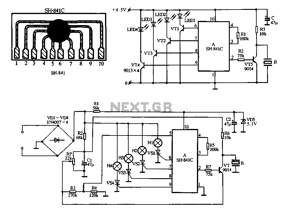
Figure 2-78 illustrates the SH-841 as the central component in a holiday lights controller. It utilizes SCRs VS1 to VS4 to drive light strings H1 to H4, causing them to flash. The operating voltage is sourced from AC through...
The drawing below illustrates a multistage light sequencer using discrete components and no integrated circuits. The concept is not new; a similar circuit was developed approximately 40 years ago using germanium transistors. The design connects the lights so that...
This Adjustable Strobe Light is the bigger brother of the plain old strobe light. This one uses a much more powerful "horse shoe" Xenon tube which produces more light. You can also control the flash rate up to about...
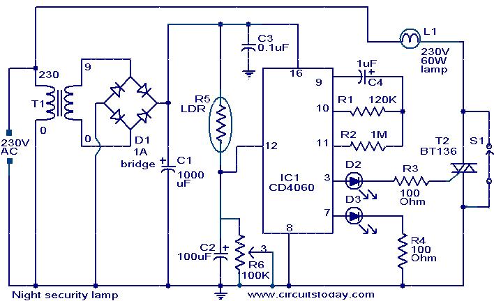
This simple circuit is built around a CMOS IC 4060 to obtain the required timing. During daytime, the LDR has low resistance and keeps pin 12 of IC1 high, preventing IC1 from oscillating. When it is dark, the LDR...
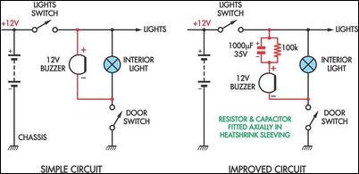
These two headlight reminder circuits are easy to install and operate on the KISS (Keep It Simple Stupid) principle. The simple circuit involves adding a 12V piezo buzzer between the lights circuit and a door switch. The buzzer sounds...