
simple headlight reminders
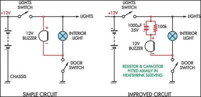
The headlight reminder circuit is designed to enhance vehicle safety by alerting drivers when headlights are left on, preventing battery drain. The basic configuration utilizes a 12V piezo buzzer connected to the vehicle's light circuit and a door switch. This arrangement ensures that the buzzer activates whenever the vehicle's lights are on and the door is opened, providing an audible reminder to the driver.
In the original simple circuit, the continuous sound of the buzzer can be distracting if the driver wishes to keep the door open, such as during a stop. To mitigate this, the improved version of the circuit introduces a 1000 µF capacitor and a 100 kΩ resistor. The capacitor serves as a temporary power source that allows the buzzer to emit a short sound when the door is opened, rather than a continuous tone. This is achieved as the capacitor charges quickly, generating a brief audible alert.
The 100 kΩ resistor plays a critical role in the circuit by discharging the capacitor when the vehicle's lights are turned off. This ensures that the capacitor is reset and ready for the next activation, maintaining the functionality of the reminder system without causing prolonged disturbances.
The overall design adheres to the KISS principle, making it user-friendly while effectively preventing potential battery issues caused by forgotten headlights. The simplicity of the circuit allows for easy installation, making it an ideal solution for enhancing vehicle safety.These two headlight reminder circuits are easy to install and operate on the KISS (Keep It Simple Stupid) principle. The simple circuit involves adding just a 12V piezo buzzer between the lights circuit and a door switch.
The buzzer sounds if the lights are left on and you open a door. The disadvantage of this simple circuit is that it`s annoying to have the buzzer sound continuously if you want to leave the door open while the lights are on. The improved circuit overcomes that problem by adding a 1000 µF capacitor and a parallel 100kO resistor in series with the buzzer. Now, when a door is opened, the buzzer gives a brief burst of sound only, while the 1000 µF capacitor charges.
The 100kO resistor discharges the capacitor when the lights are switched off. 🔗 External reference
Related Circuits

The circuit utilizes a dual operational amplifier integrated circuit (IC), specifically the 1458, which contains two separate op-amps within a single package. In this configuration, the first op-amp functions as a voltage follower, directing its output to charge capacitor...
Do you drive an older car without an automatic "lights-on" warning circuit? If so, you have probably accidentally left the lights on and drained the battery on one or more occasions. This headlights reminder circuit will prevent that. It...
An AM modulator for the medium wave (MW) band enables playback of music from a CD or MP3 player on compatible radios during the daytime. This device is not classified as a transmitter due to its low output power...

The circuit employs a field-effect transistor (FET) at the input of a Schmitt trigger, allowing the use of a low-value capacitor. The trigger, controlled by Q1 and O2, exhibits a hysteresis of approximately 3V, regulated by a 3V zener...
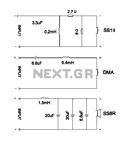
The divider acts as the speaker's brain and is crucial for sound quality. The music amplifier's output signal must be processed through a wave filter element to divide it into specific frequency signals for each unit. A scientifically and...
This temperature controller utilizes an LM135/235/335 temperature sensor and is designed to maintain a small environment at a warm or hot temperature. A schematic diagram is provided. The temperature controller circuit is centered around the LM135/235/335 series of temperature sensors,...
Warning: include(partials/cookie-banner.php): Failed to open stream: Permission denied in /var/www/html/nextgr/view-circuit.php on line 713
Warning: include(): Failed opening 'partials/cookie-banner.php' for inclusion (include_path='.:/usr/share/php') in /var/www/html/nextgr/view-circuit.php on line 713