
nimh charger for up to six
The charger circuit for NiMH batteries utilizes the MAX712 integrated circuit, which incorporates features necessary for efficient charging. The design includes a current regulation mechanism through transistor T1, ensuring that the charging current remains stable. Resistor R1 plays a crucial role in current measurement, allowing the IC to maintain a consistent voltage across it, thereby enabling precise control of the charging process.
The charger is designed to accommodate various battery configurations, as indicated by the user-programmable inputs. This flexibility is essential for households that may utilize different battery types and capacities. The inclusion of dongles simplifies the setup process, allowing users to easily adjust the charging parameters without extensive technical knowledge.
In addition to monitoring voltage and current, the circuit can be designed to include temperature sensors to enhance safety during the charging process. This feature can prevent overheating, which is a common issue with battery charging, particularly with older battery technologies.
Overall, this battery charger circuit exemplifies modern engineering practices in consumer electronics, emphasizing efficiency, safety, and user-friendliness. The transition from NiCd to NiMH batteries reflects broader trends in environmental consciousness and technological advancement, making this charger a relevant and necessary component in contemporary households.It is impossible to imagine present day society without any batteries. Count the number of gadgets in your house that are powered from batteries, you will be stunned by the number of batteries you will find. The majority of these devices use penlight batteries and if you`re a little environmentally conscious you will be using rechargeable batterie
s. A few years ago these batteries were invariably NiCd types. However, these batteries suffer from a relatively high rate of self-discharge and from the so-called memory-effect. It is now more common to use NiMH batteries. The advantage is that these batteries do not suffer from the memory-effect and generally also have a much higher capacity, so that they last longer before they have to be recharged again.
From the above you can conclude that every household these days needs, or could use, a battery charger. A good charger needs to keep an eye on several things to ensure that the batteries are charged properly.
For one, the charger has to make sure that the voltage per cell is not too high. It also needs to check the charging curve to determine when the battery is fully charged. If the charging process is taking too long, this is an indication that something is wrong and the charger must stop charging. Sometimes it is also useful to monitor the temperature of the cells to ensure that they do not get too hot.
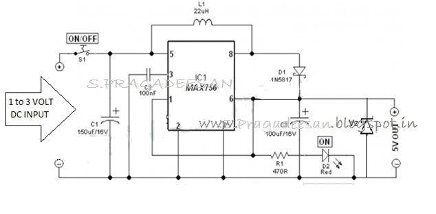
The circuit presented here is intended for charging NiMH batteries. The MAX712 IC used here contains all the necessary functionality to make sure that this happens in a controlled manner. Figure 1 shows the schematic of the charger. The heart of the circuit is easily recognized: everything is arranged around IC1, a MAX712 from Maxim.
This IC is available in a standard DIP package, which is convenient for the hobbyist because it can be directly fitted on standard though-hole prototyping board. IC1 uses T1 to regulate the current in the battery. R1 is used by IC1 to measure the current. While charging, IC1 attempts to maintain a constant voltage, equal to 250 mV, across R1. By adjusting the value of R1 the charging current can be set. The value of R1 can be calculated using the formula below: R1 = 250 mV / I charge For a charging current of 1 A, the value of R1 has to be 250 mV / 1 A = 0.
25 . The power dissipated by R1 equals U G— I = 0. 25 G— 1= 250 mW. A 0. 5-watt resistor will therefore suffice for R1. Transistor T1 may need a small heatsink depending on the charging current and supply voltage. IC1 needs a small amount of user input regarding the maximum charging time and the number of cells in the battery to be charged. IC1 has four inputs, PGM0 to PGM3, for this purpose. These are not ordinary digital inputs (which recognise only 2 states) but special inputs that recognise 4 different states, namely V+, Vref, BATT or not connected.
To make this a little bit more user friendly, we`ve brought out the necessary connections to 2 connectors (K3 and K4). A number of dongles have been made (Figure 2) that can be plugged into these connectors and set the number of cells and the maximum charging time.
When determining the maximum charging time we have to take into account the charging current and the capacity of the cells that are connected. The charging time can be calculated with the formula: Tcharge = Ccell / I charge G— 1. 2 where Ccell is the capacity in Ah (e. g. , 1200 mAh = 1. 2 Ah). After the nominal charging time has been calculated, we can use the first dongle that has a value that is equal or greater than the calculated charging time.
For example, if we calculated a maximum charging time of 38 minutes, we have to select the dongle for 45 minutes. When IC1 is replaced by a MAX713, the charger becomes suitable for charging NiCd batteries (but not suitable for NiMH batteries any more!).
The only difference between these two ICs is the value of the detection point at which the cell(s) are considered to be completely charged. The ICs are otherwise identical with regard to pin-out, method of adjustment, etc. To make it easy to swap between the ICs, we recommend an IC-socket for IC1. 🔗 External reference
Related Circuits
Every innovation begins with a simple everyday problem, such as watching an IPL match on TV when suddenly the power goes out, prompting the search for an alternative way to watch via mobile network. Similarly, a frequent issue of...
This project involves a mini USB car charger circuit that is simple to construct using only three components. The core of the circuit is the LM78M05 integrated circuit (IC), which is a 5V positive voltage regulator. This IC includes...
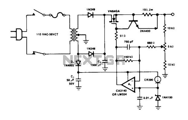
The operational amplifier A1 directly drives the VN64GA with the error signal to control the output voltage. The peak rectifier D1 and capacitor C1 supply the error amplifier A1 and the reference zener. This additional drive voltage must exceed...

This type of charger transfers RF energy from an inductor (L2) to an external pickup coil. The pickup coil is connected to a rectifier and a battery that requires charging. This design is advantageous as it eliminates the need...
Charging a mobile phone or cellphone battery presents a significant challenge while traveling, as a power supply source is often not readily available. If the cellphone remains switched on continuously, its battery can deplete within five to six hours,...
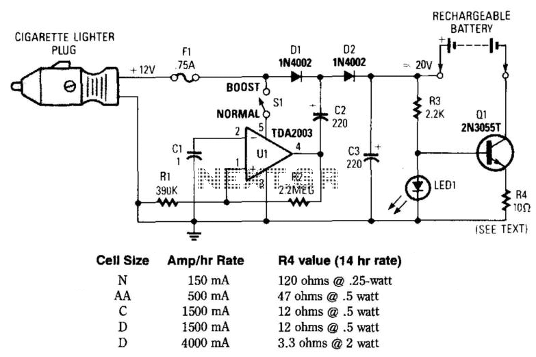
This circuit provides an output of up to 20 V from a 12-V automotive supply, enabling constant current charging of NiCad battery assemblies with a total voltage of approximately 18 V. The circuit utilizes a square-wave oscillator (VI) and...