
usb car charger
The mini USB car charger circuit is designed to efficiently convert the higher voltage from a car battery (typically 12V DC) to a lower, safer voltage suitable for USB-powered devices (5V DC). The LM78M05 voltage regulator serves as the primary component, providing a stable output voltage while incorporating essential safety features to protect both the circuit and the connected devices.
The circuit layout typically includes the LM78M05 IC, input and output capacitors, and a connection point for the cigarette lighter socket. The input capacitor, usually a ceramic or electrolytic capacitor, is connected to the input pin of the LM78M05 to filter any high-frequency noise and stabilize the input voltage. The output capacitor, also placed close to the output pin, helps to maintain a steady output voltage under varying load conditions.
The output current rating of 500mA indicates that the circuit can charge devices such as smartphones, tablets, and other USB gadgets efficiently. For applications requiring higher output current, alternative configurations using different voltage regulators or additional components may be employed, such as the mentioned 12V to 9V converter capable of delivering 1000mA.
To ensure the reliability and safety of the circuit, it is crucial to follow proper wiring practices and verify the output voltage with a multimeter before connecting any devices. This precaution helps to avoid potential damage to sensitive electronics due to incorrect voltage levels. Overall, this mini USB car charger circuit represents a practical solution for charging USB devices on the go, leveraging the car's battery power efficiently.This is a project of a mini USB car charger circuit. The circuit is very simple to build using only three components. Heart of the circuit is a LM78M05 IC which is a 5V positive voltage regulator IC. This IC has many built in featuers like thermal overload protection, short circuit protection, safe operating area protection etc. The circuit can b e easily connected with the cigar socket in car and convert 12 volt DC to 5 volt DC and charge many USB devices. Out put current of the circuit is 500mA which is enough to charge any USB device. The circuit is basically a DC to DC converter and can also be used to run many 5 to 6 volt DC device from car battery.
There are also other similar circuits which you can use to run any 5V or 9V devices from car battery like 12V to 5V converter and 12V to 9V converter with 1000mA output current. Note: It is adviced to check and confirm the connections and 5 volt output voltage of the circuit with multimeter before connecting any USB device for charging to make sure the circuit is working fine without any soldering or wiring error and providing 5 volt DC output.
🔗 External reference
Related Circuits
The circuit was constructed on a Vero board and tested with a large electrolytic capacitor in place of a battery. A 500-ohm preset resistor determines the output voltage, while a 47k preset resistor regulates the hysteresis and establishes the...
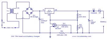
To set up the charging voltage, power on the charger and connect a voltmeter across the output terminals. Adjust R4 until the voltmeter reads 28V. The charger is now ready for battery connection. The charging circuit described involves a voltage...

This circuit provides a simple and efficient method to draw current from a motorcycle battery to charge a mobile phone. Most mobile phone battery packs consist of three 1.2-volt cells, resulting in a total voltage of 3.6 volts. For...
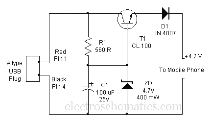
A mobile phone can be charged using the USB outlet of a PC. This simple USB cellphone charger circuit provides a regulated output of 4.7 volts for charging the mobile phone. The USB outlet typically supplies 5 volts DC...
The circuit is designed to be powered directly by a power supply, which is why it does not include a transformer, rectifier, or filter capacitors in the schematic. However, these components can be added if desired. To operate the...
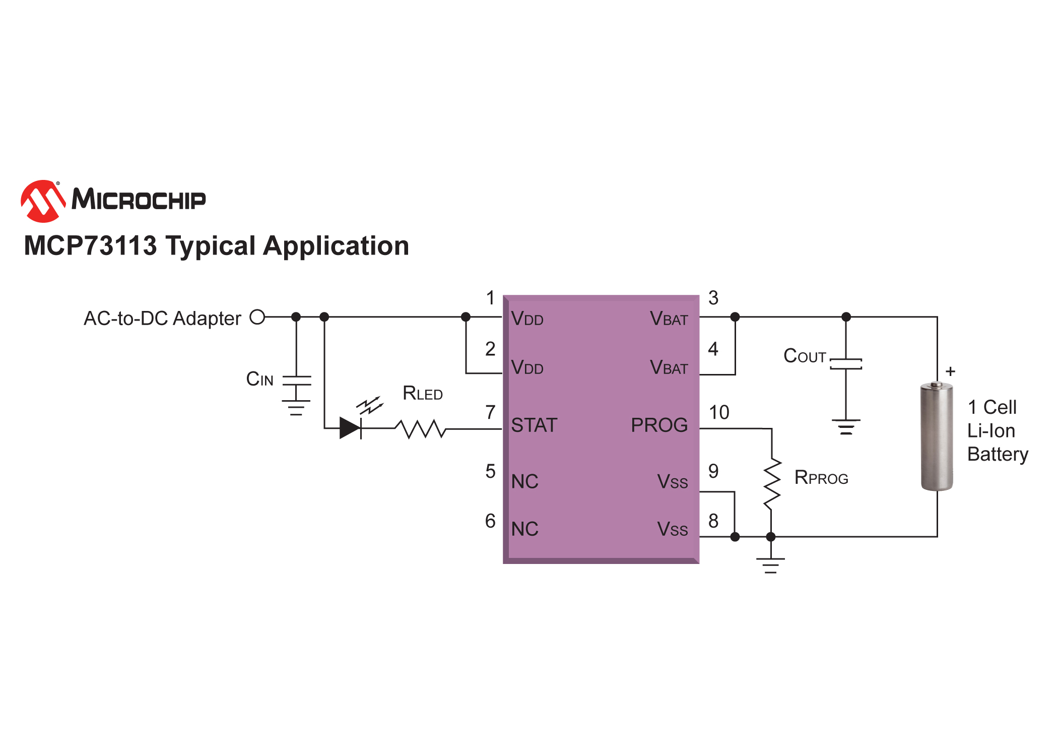
Microchip Technology's MCP73113, MCP73114, and MCP73213 Lithium-Ion (Li-Ion) chargers, as well as the MCP73123 and MCP73223 Lithium Iron Phosphate (LiFePO4) chargers, are equipped with Overvoltage Protection (OVP) to prevent overheating and damage to the battery-charger circuit from input voltage...