
Solid-state electric fence charger
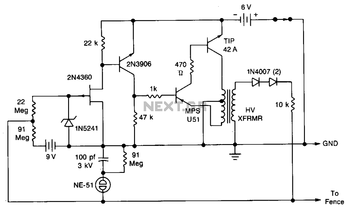
The described touch-sensing circuit employs a high-voltage generator that is crucial for perimeter security applications. The circuit is designed to remain inactive until a disturbance is detected, which is achieved through the touch-sensing mechanism. The core component of the circuit is the high-voltage generator, which is responsible for producing short, high-voltage pulses. These pulses are delivered to the fence wire to create a deterrent against intruders.
The circuit operates by monitoring the resistance between the fence wire and the earth ground. When an intruder touches the wire, their body provides a path to ground, which reduces the resistance. This change in resistance is detected by the circuit, triggering the high-voltage generator to activate. The generator then sends 500-microsecond pulses at a voltage level of approximately 300 volts. The frequency of these pulses is directly correlated to the intruder's resistance; thus, a lower resistance results in a higher frequency of pulses, enhancing the deterrent effect.
A ground rod is strategically placed near the fence to ensure effective grounding and to minimize false triggers. The neon lamp acts as an indicator of the circuit's operational status. In normal operation, the lamp should remain off, indicating that there is no leakage current between the fence wire and the ground. If the lamp illuminates or flickers, this suggests that there is an unintended path for current flow, which could lead to false alarms or reduced effectiveness of the circuit.
To fine-tune the sensitivity of the circuit, a resistor is employed. The default resistor value is set at 91 Megohms; however, if the sensitivity proves to be excessive—resulting in false triggers—the resistance can be decreased by substituting the 91 Megohm resistor with a 47 or 22 Megohm resistor. This adjustment allows for greater control over the circuit's responsiveness to disturbances, ensuring that it remains effective without being overly sensitive to environmental factors.
In summary, this touch-sensing circuit is a sophisticated solution for enhancing security through the use of high-voltage pulses, effectively combining electrical engineering principles with practical applications in perimeter protection.A touch-sensing circuit keeps the high-voltage generator cut off until something touches the fence wire. Contact with the fence sensing circuit wire starts the high-voltage generator which applies a series of 500 microsecond pulses at approximately 300 volts to the fence wire.
Pulse repetition rate is determined by the intruder's resistance to earth ground. The lower the resistance, the higher the pulse rate. A ground rod is inserted several inches into the ground near the fence wire. In the sensing mode the neon lamp should not flicker or light. If it does, it indicates leakage between the fence wire and ground. If sensitivity is too great, it can be reduced by changing the 91 Meg resistor to 47 or 22 Meg as required. 🔗 External reference
Related Circuits
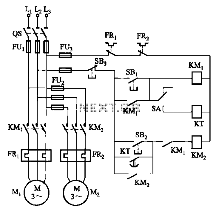
The circuit illustrated in Figure 3-85 features both manual and automatic control through the transfer switch SA. After initiating the motor Mi, an automatic start sequence is achieved via the time relay KT. The circuit employs a transfer switch (SA)...
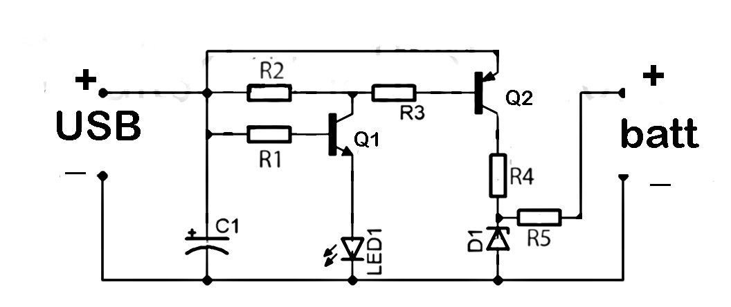
This document discusses the series used in USB connections for charging batteries. The output voltage ranges from 4.7 volts to 5 volts DC, which is suitable for charging mobile phones and other battery types. The circuit described enhances the...
This is a straightforward circuit designed for charging lead-acid batteries using the PB137 regulator. The PB137 is utilized in the lead-acid battery charger circuit due to its ability to provide... The PB137 voltage regulator is a linear regulator specifically suited...
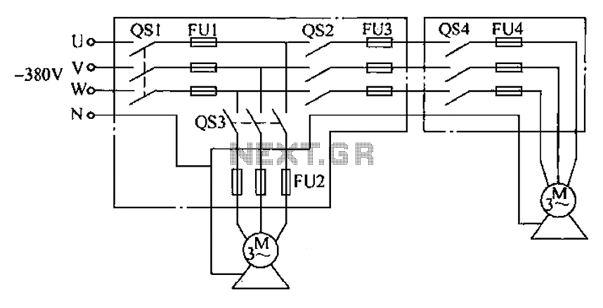
The agriculture and electrical power harrow plow power cord must consist of four rubber cables, with one core wire designated as the ground wire. The traction machine housing must be properly grounded. The two traction power machines are connected...
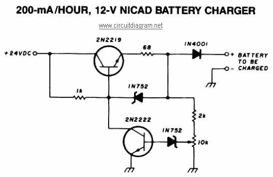
A 12V NiCAD battery charger circuit with a charging rate of 200mA per hour. This circuit initially charges the battery at 75mA until it reaches a full charge, after which the current is reduced to a trickle rate. The...
This very simple circuit uses a transformer, two diodes, a capacitor, and an ammeter. To charge a battery, just connect the + and - terminals of the circuit to the corresponding terminals of the battery. When the battery is...