
NMEA 2000 CAN Marine Interface
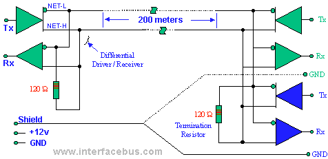
The CAN Bus (Controller Area Network) interface is a robust vehicle bus standard designed for real-time communication among microcontrollers and devices without a host computer. The asynchronous nature of the transmission allows for efficient data transfer, particularly in environments with high electrical noise, such as automotive applications.
The structure of the data frame is crucial for ensuring reliable communication. The Arbitration field is used to determine which node has the highest priority to transmit data when multiple nodes attempt to send messages simultaneously. The Control field specifies the type of data being sent, while the Data field carries the actual information, which can vary in length from 0 to 8 bytes, depending on the application requirements.
The CRC field plays a vital role in maintaining data integrity by detecting errors that may occur during transmission. The polynomial used in the CRC calculation is designed to provide a high level of error detection capability. The acknowledgment (ACK) field allows the receiving node to confirm successful receipt of the message, thereby enhancing the reliability of the communication process.
Error detection in the CAN protocol is comprehensive. At the message level, CRC checks ensure that the data has not been corrupted during transmission. Frame checks verify the integrity of the entire message format, while acknowledgment checks confirm that the intended recipient has received the data. At the bit level, Bit Monitoring ensures that the transmitted bits conform to expected values, while Bit Stuffing prevents long sequences of identical bits that could lead to synchronization issues.
Overall, the CAN Bus interface is a highly effective communication protocol that provides a reliable method for data exchange in complex systems, particularly in automotive and industrial applications. Its sophisticated error detection mechanisms and structured data frame format contribute to its widespread adoption in various electronic systems.The CAN Bus interface uses an asynchronous transmission scheme controlled by start and stop bits at the beginning and end of each character. This interface is used, employing serial binary interchange. Information is passed from transmitters to receivers in a data frame. The data frame is composed of an Arbitration field, Control field, Data field , CRC field, ACK field. The frame begins with a `Start of frame` [SOF], and ends with an `End of frame` [EOF] space. The data field may be from 0 to 8 bits. The frame check sequence is derived from a Cyclic Redundancy Code (CRC); the coefficients are generated modulo-2: X15 + X14 + X10 + X8 + X7 + X4 + X3 + 1. CAN implements five error detection mechanisms; 3 at the message level and 2 at the bit level [Also incorporates error flags].
At the message level: Cyclic Redundancy Checks (CRC), Frame Checks, Acknowledgment Error Checks. At the bit level: Bit Monitoring, Bit Stuffing. 🔗 External reference
Related Circuits
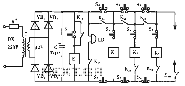
The circuit operates as illustrated in Figure 5-2a. It includes an alarm switch (S). When switch S is pressed, relay K is activated, which closes two normally open contacts. This action triggers the alarm bells. The alarm continues to...
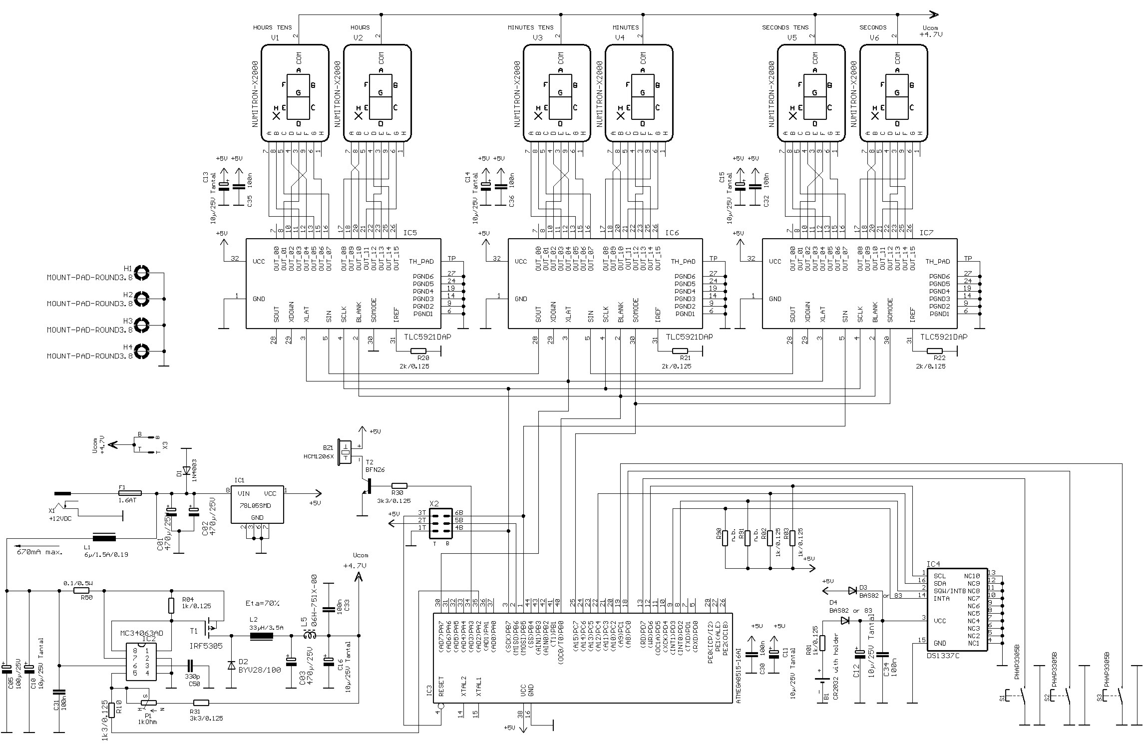
Numitrons are display devices similar to Nixie tubes, specifically designed for low voltage applications. They function as incandescent displays, utilizing filaments for the segments. A typical seven-segment readout comprises seven narrow illuminated bars arranged to create a rectangular figure...
Audio can be extracted from a telephone line using a transformer and a capacitor to isolate the line from external equipment. A non-polarized capacitor is placed in series with the transformer line connection to prevent direct current from flowing...
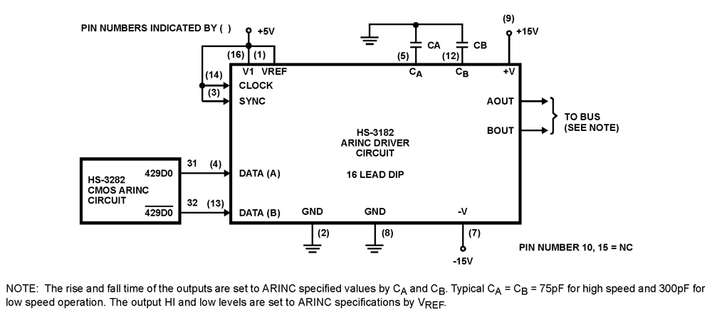
The HS-3182 is a monolithic dielectrically isolated bipolar differential line driver designed to meet the specifications of ARINC 429. This device is intended to be used with a companion chip, the HS-3282 CMOS ARINC Bus Interface Circuit, which provides...

This joystick model was introduced by IBM alongside their first IBM PC computer. It is a basic analog joystick featuring two buttons. The original joystick interface included a circuit for connecting two joysticks but only had one joystick connector....
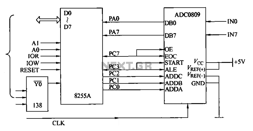
The ADC0809 is an 8-channel analog switch integrated with an 8-bit successive approximation analog-to-digital (A/D) converter. It supports the selection of eight input channels through address latch and encoder channel selection signals ADDA, ADDB, and ADDC. The address latch...