
Simple lock circuit can alarm
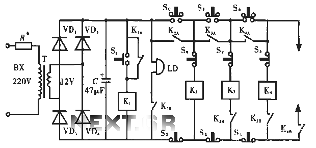
The described circuit is a security system integrating an alarm mechanism with an electronic locking feature. The primary components include several relays (K, K2, K3, and K4), normally open and normally closed push-button switches (S, S6, S7, S8, and S9), and an electronic lock. The operation begins with the activation of switch S, which triggers relay K. This relay's activation closes its contacts, initiating the alarm system. The alarm remains active until the power is manually cut off, ensuring that any unauthorized access is promptly signaled.
The inclusion of relay K2 allows for the control of additional electrical appliances once switch S is engaged. The relay contacts K2A and K2B are crucial for this function, as they facilitate the flow of electricity to the connected devices. The subsequent action of pressing switch S6 energizes relay K4, which is essential for engaging the electronic lock mechanism. The lock is designed to operate smoothly, thanks to the closure of contacts K4A and K4B, which complete the circuit necessary for unlocking.
It is critical to adhere to the specified sequence of operations for switches S8 and S6, as reversing this order will render the circuit inoperative. The system is designed with safety in mind, utilizing normally closed switches to prevent accidental unlocking. This feature ensures that the circuit remains secure unless a deliberate action is taken to unlock it.
The system also includes a customizable password feature, allowing users to set their own unlock code, enhancing the security of the electronic lock. The default code of "086" serves as a starting point, but users are encouraged to change it to a more secure option to prevent unauthorized access. Overall, this circuit design exemplifies a robust approach to security, combining alarm functionality with electronic locking capabilities in a single schematic.Circuit works: Figure 5 -2a in S. Alarm switch. If you press S, after the relay K. Electrical work, two normally open contacts Pull, so that the alarm bells sound. At this time, even when you release s. Alarm sound is still large, and so only after the arrival of the owner off the power to stop the alarm. so, S. , S6 valid switch. After pressing so, K2 relay energized electrical appliances, two normally open contacts K2A, Kze pull; and finally press S6, K4 relay is to energize, K.
A, K4B normally open contact sticking, thereby turning on the power smoothly electronic lock to open the lock. Note that so, s8, S6 open order can not be reversed, otherwise invalid. S: a S ,, S7, S9 are normally closed push button switch, unlocking switch can not be pressed several, whether the circuit is broken, K2, K3, K4 relay re-energized.
The schematic set unlock password is "086", of course, readers can also reset the password lock.
Related Circuits
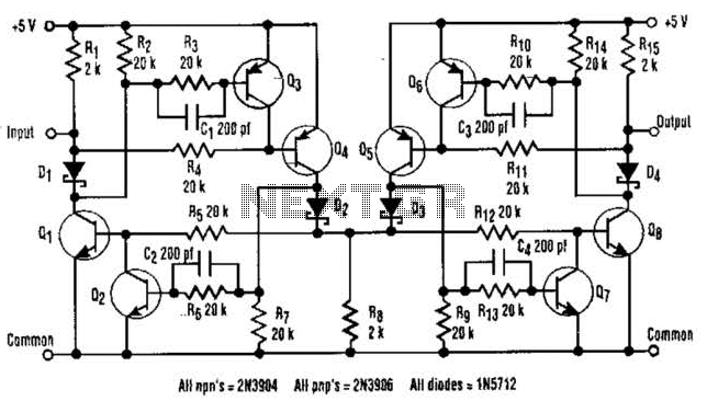
The I2C serial bus is a widely used two-wire bus for small-area networks. The I2C Clock and Data lines feature open collector (or drain) outputs for each device on the network, requiring only a single pull-up resistor. This architecture...
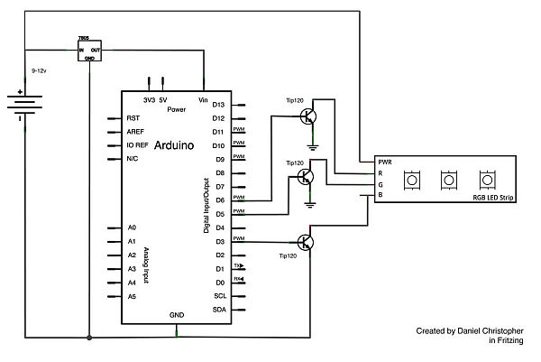
This document outlines the assembly of a circuit designed to pulse width modulate (PWM) a high-power RGB LED strip and program an Arduino to cycle through various colors. The term "high power" refers to a voltage range of 9-12...
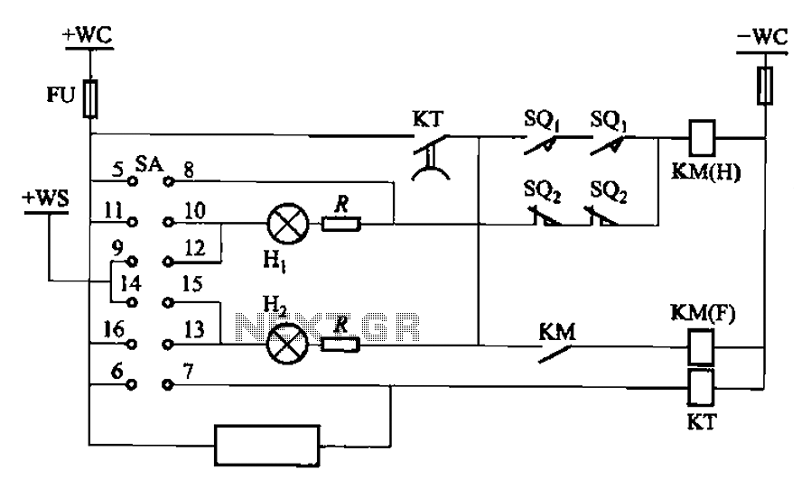
The BT9404 is a de-excitation type switch utilized with CJ4-S contactors and JT3-21/3-type electromagnetic relays. The control circuit is depicted in Figure 7-55. The KM contactors used are CJ4-S, while the time relay is the JT3-21/3. The SA component...
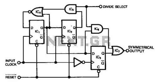
This circuit generates a symmetrical waveform by dividing the input frequency by either 2 or 3. The Divide Select input governs the division factor. When the Divide Select input is high, flip-flops IC1 and IC2, along with the associated...
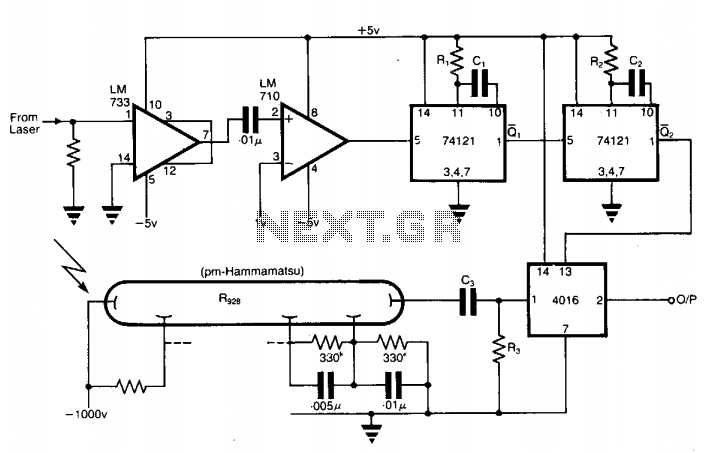
The application involves observing the light pulse emerging from a thick specimen after transillumination by a laser pulse. Pulses derived from the laser source are amplified using a Video Amplifier LM733. The reference level is set to 1 V...
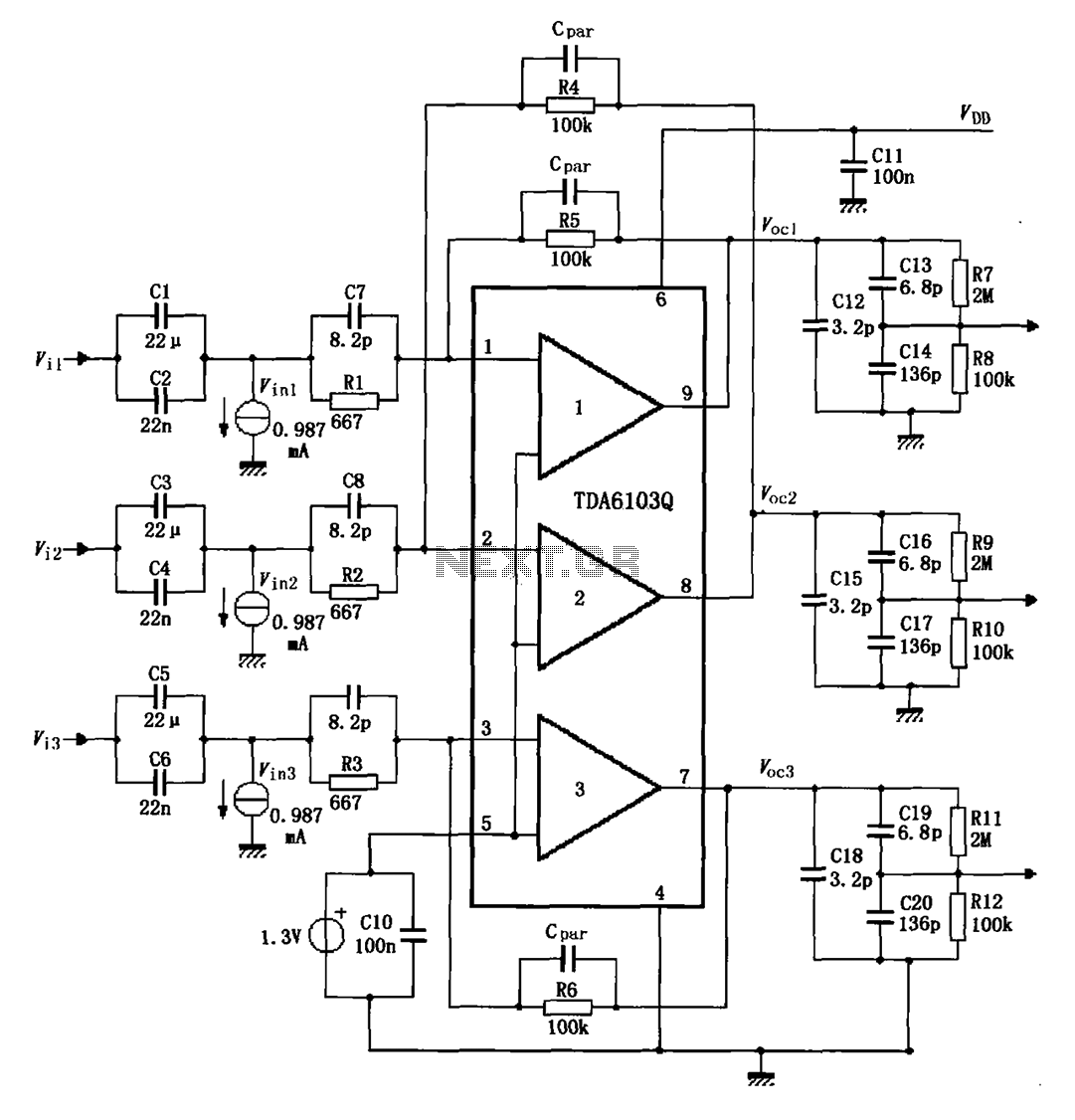
The TDA6103Q test circuit features a feedback factor of 1/150. Input signals Vi1, Vi2, and Vi3 are directed through an input resistor network that includes capacitors to the TDA6103Q pins 1, 2, and 3, which are part of the...